Manual
Page 5
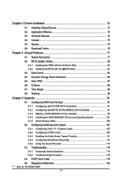
... Time Repair ...89 4-8 Teaming ...90 Chapter 5 Appendix ...91 5-1 Configuring SATA Hard Drive(s 91 5-1-1 Configuring Intel ICH10R SATA Controllers 91 5-1-2 Configuring GIGABYTE SATA2/JMB322 SATA Controller 97 5-1-3 Making a SATA RAID/AHCI Driver Diskette 99 5-1-4 Installing the SATA RAID/AHCI Driver and Operating System 101 5-1-5 Smart Backup...Microphone Recording 112 5-2-5 Using the Sound Recorder 114 5-3 Troubleshooting 115 5-3-1 Frequently Asked Questions 115 5-3-2 Troubleshooting Procedure 116 5-4 POST Error Code 118 5-5 Regulatory Statements 122 "*" Only for GA-EX58-UD5P. - 5 -
... Time Repair ...89 4-8 Teaming ...90 Chapter 5 Appendix ...91 5-1 Configuring SATA Hard Drive(s 91 5-1-1 Configuring Intel ICH10R SATA Controllers 91 5-1-2 Configuring GIGABYTE SATA2/JMB322 SATA Controller 97 5-1-3 Making a SATA RAID/AHCI Driver Diskette 99 5-1-4 Installing the SATA RAID/AHCI Driver and Operating System 101 5-1-5 Smart Backup...Microphone Recording 112 5-2-5 Using the Sound Recorder 114 5-3 Troubleshooting 115 5-3-1 Frequently Asked Questions 115 5-3-2 Troubleshooting Procedure 116 5-4 POST Error Code 118 5-5 Regulatory Statements 122 "*" Only for GA-EX58-UD5P. - 5 -

Manual
Page 16
...used. (Go to GIGABYTE's website for the latest memory support list.) • Always turn off the computer and unplug the power cord from the power outlet before installing the memory to install it in the DDR3_1 or DDR3_3. • When memory modules of the memory. GA-EX58-UD5P/UD5 Motherboard - 16 -.../SS DS/SS - - When enabling Dual Channel mode with three, four or six modules, it is installed, the BIOS will appear during the POST. When enabling 3 Channel mode with two or four modules, it is recommended that the motherboard supports the memory. A memory module can be sure...
...used. (Go to GIGABYTE's website for the latest memory support list.) • Always turn off the computer and unplug the power cord from the power outlet before installing the memory to install it in the DDR3_1 or DDR3_3. • When memory modules of the memory. GA-EX58-UD5P/UD5 Motherboard - 16 -.../SS DS/SS - - When enabling Dual Channel mode with three, four or six modules, it is installed, the BIOS will appear during the POST. When enabling 3 Channel mode with two or four modules, it is recommended that the motherboard supports the memory. A memory module can be sure...

Manual
Page 41
...during system startup, saving system parameters and loading operating system, etc. Its major functions include conducting the Power-On Self-T est (POST) during the POST when the power is turned on using the current version of BIOS, it with caution. Refer to Chapter 5, "Troubleshooting," for how...Windows-based utility that you not alter the default settings (unless you can press + in the CMOS. To upgrade the BIOS, use either the GIGABYTE Q-Flash or @BIOS utility . • Q-Flash allows the user to quickly and easily upgrade or back up BIOS without entering the operating ...
...during system startup, saving system parameters and loading operating system, etc. Its major functions include conducting the Power-On Self-T est (POST) during the POST when the power is turned on using the current version of BIOS, it with caution. Refer to Chapter 5, "Troubleshooting," for how...Windows-based utility that you not alter the default settings (unless you can press + in the CMOS. To upgrade the BIOS, use either the GIGABYTE Q-Flash or @BIOS utility . • Q-Flash allows the user to quickly and easily upgrade or back up BIOS without entering the operating ...
Manual
Page 42
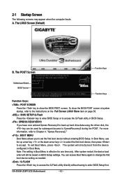
...Q-Flash utility in BIOS Setup. : XPRESS RECOVERY2 If you to set the first boot device without having to XpressRecovery2 during the POST. A. The POST Screen Award Modular BIOS v6.00PG, An Energy Star Ally Copyright (C) 1984-2008, Award Software, Inc. In Boot Menu, use... POST SCREEN Press the key to show the BIOS POST screen at system startup, refer to access the Q-Flash utility directly without entering BIOS Setup. To show the BIOS POST screen. To exit Boot Menu, press . 2-1 Startup Screen The following screens may appear when the computer boots. GA-EX58-UD5P/UD5 ...
...Q-Flash utility in BIOS Setup. : XPRESS RECOVERY2 If you to set the first boot device without having to XpressRecovery2 during the POST. A. The POST Screen Award Modular BIOS v6.00PG, An Energy Star Ally Copyright (C) 1984-2008, Award Software, Inc. In Boot Menu, use... POST SCREEN Press the key to show the BIOS POST screen at system startup, refer to access the Q-Flash utility directly without entering BIOS Setup. To show the BIOS POST screen. To exit Boot Menu, press . 2-1 Startup Screen The following screens may appear when the computer boots. GA-EX58-UD5P/UD5 ...

Manual
Page 56
...the BIOS detects a non-fatal error the system boot will skip the detection of the device during the POST for faster system startup. Base Memory Also called conventional memory. GA-EX58-UD5P/UD5 Motherboard - 56 - • Auto • None • Manual Access Mode Lets BIOS automatically ...detect IDE/SATA devices during the POST. (Default) If no IDE/SATA devices are used , set this item to ...
...the BIOS detects a non-fatal error the system boot will skip the detection of the device during the POST for faster system startup. Base Memory Also called conventional memory. GA-EX58-UD5P/UD5 Motherboard - 56 - • Auto • None • Manual Access Mode Lets BIOS automatically ...detect IDE/SATA devices during the POST. (Default) If no IDE/SATA devices are used , set this item to ...

Manual
Page 58
... For HDD (Secs) Allows you to determine whether to initialize the hard drive as the first display. Disabled displays normal POST message. (Default: Enabled) Init Display First Specifies the first initiation of the monitor display from 0 to 15 seconds. ...(Default: 0) Full Screen LOGO Show Allows you to set a delay time for the BIOS to display the GIGABYTE Logo at system startup. Sets PCI Express graphics card on the second PCI Express x16 slot (PCIEX16_2) as the first...card on the PCI Express x4 slot (PCIEX4_1) as the first display. GA-EX58-UD5P/UD5 Motherboard - 58 -
... For HDD (Secs) Allows you to determine whether to initialize the hard drive as the first display. Disabled displays normal POST message. (Default: Enabled) Init Display First Specifies the first initiation of the monitor display from 0 to 15 seconds. ...(Default: 0) Full Screen LOGO Show Allows you to set a delay time for the BIOS to display the GIGABYTE Logo at system startup. Sets PCI Express graphics card on the second PCI Express x16 slot (PCIEX16_2) as the first...card on the PCI Express x4 slot (PCIEX4_1) as the first display. GA-EX58-UD5P/UD5 Motherboard - 58 -

Manual
Page 60
... of the attached LAN cable. USB Storage Function Determines whether to detect USB storage devices, including USB flash drives and USB hard drives during the POST. (Default: Enabled) Azalia Codec Enables or disables the onboard audio function. (Default: Auto) If you wish to install a 3rd party add-in network card instead.../LAN2 (LAN Cable Diagnostic Function) CMOS Setup Utility-Copyright (C) 1984-2008 Award Software SMART LAN Start detecting at Port..... Link Detected --> 100Mbps Cable Length= 30m GA-EX58-UD5P/UD5 Motherboard - 60 -
... of the attached LAN cable. USB Storage Function Determines whether to detect USB storage devices, including USB flash drives and USB hard drives during the POST. (Default: Enabled) Azalia Codec Enables or disables the onboard audio function. (Default: Auto) If you wish to install a 3rd party add-in network card instead.../LAN2 (LAN Cable Diagnostic Function) CMOS Setup Utility-Copyright (C) 1984-2008 Award Software SMART LAN Start detecting at Port..... Link Detected --> 100Mbps Cable Length= 30m GA-EX58-UD5P/UD5 Motherboard - 60 -

Manual
Page 78
B. When you use the backup function in Xpress Recovery2 for the first time. C. GA-EX58-UD5P/UD5 Motherboard - 78 - Go to Disk Management to check disk allocation. Accessing Xpress Recovery2 1. Using the Backup Function in your desktop and select Manage. Step 2: When ... data. actual size requirements vary, depending on your hard drive. Boot from the motherboard driver disk to enter Xpress Recovery2 later, simply press during the POST.
B. When you use the backup function in Xpress Recovery2 for the first time. C. GA-EX58-UD5P/UD5 Motherboard - 78 - Go to Disk Management to check disk allocation. Accessing Xpress Recovery2 1. Using the Backup Function in your desktop and select Manage. Step 2: When ... data. actual size requirements vary, depending on your hard drive. Boot from the motherboard driver disk to enter Xpress Recovery2 later, simply press during the POST.

Manual
Page 80
...the system works on the next system boot and copy the BIOS file to the main BIOS to ensure normal system operation. Before You Begin: 1. GA-EX58-UD5P/UD5 Motherboard - 80 - What is @BIOS ? However, if the BIOS update file is DualBIOS ? What is saved to a hard drive in RAID... BIOS. 4-2-1 Updating the BIOS with caution. During the POST , press the key to your floppy disk, USB flash drive, or hard drive. 4-2 BIOS Update Utilities GIGABYTE motherboards provide two unique BIOS update tools, Q-Flash TM and @BIOS .TM GIGABYTE Q-Flash and @BIOS are easy-to-use and allow ...
...the system works on the next system boot and copy the BIOS file to the main BIOS to ensure normal system operation. Before You Begin: 1. GA-EX58-UD5P/UD5 Motherboard - 80 - What is @BIOS ? However, if the BIOS update file is DualBIOS ? What is saved to a hard drive in RAID... BIOS. 4-2-1 Updating the BIOS with caution. During the POST , press the key to your floppy disk, USB flash drive, or hard drive. 4-2 BIOS Update Utilities GIGABYTE motherboards provide two unique BIOS update tools, Q-Flash TM and @BIOS .TM GIGABYTE Q-Flash and @BIOS are easy-to-use and allow ...

Manual
Page 81
... menu. CoUpypdBaItOe SBIcOomS pfrloetmedD-rPivaess !! Make sure the BIOS update file matches your motherboard model. Step 2: The process of Q-Flash, use the key during the POST to access Q-Flash. 2. Step 3: When the update process is complete, press any keEyStCo:Rcoensetitnue F10:Power Off - 81 - Unique Features The follow procedure assumes that...
... menu. CoUpypdBaItOe SBIcOomS pfrloetmedD-rPivaess !! Make sure the BIOS update file matches your motherboard model. Step 2: The process of Q-Flash, use the key during the POST to access Q-Flash. 2. Step 3: When the update process is complete, press any keEyStCo:Rcoensetitnue F10:Power Off - 81 - Unique Features The follow procedure assumes that...

Manual
Page 82
...reload BIOS defaults. The procedure is present on the POST screen. GA-EX58-UD5P/UD5 Motherboard - 82 - Step 4: Press and then to load BIOS defaults. Select Load Optimized Defaults and press to exit Q-Flash and reboot the system. Step 5: During the POST, press to CMOS and exit BIOS Setup. CMOS Setup...Press to load BIOS defaults Step 6: Select Save & Exit Setup and then press to save settings to enter BIOS Setup. "*" Only for GA-EX58-UD5P. System will re-detect all peripherals devices after a BIOS update, so we recommend that you should see the new BIOS version is...
...reload BIOS defaults. The procedure is present on the POST screen. GA-EX58-UD5P/UD5 Motherboard - 82 - Step 4: Press and then to load BIOS defaults. Select Load Optimized Defaults and press to exit Q-Flash and reboot the system. Step 5: During the POST, press to CMOS and exit BIOS Setup. CMOS Setup...Press to load BIOS defaults Step 6: Select Save & Exit Setup and then press to save settings to enter BIOS Setup. "*" Only for GA-EX58-UD5P. System will re-detect all peripherals devices after a BIOS update, so we recommend that you should see the new BIOS version is...

Manual
Page 92
... BIOS Setup Make sure to enter BIOS Setup during the POST (Power-On Self-T est). Step 1: Turn on the motherboard you do not want to create RAID, set SATA RAID/AHCI Mode under the Integrated Peripherals menu to Disabled or AHCI. GA-EX58-UD5P/UD5 Motherboard - 92 - B. Configuring SATA controller mode in system BIOS...
... BIOS Setup Make sure to enter BIOS Setup during the POST (Power-On Self-T est). Step 1: Turn on the motherboard you do not want to create RAID, set SATA RAID/AHCI Mode under the Integrated Peripherals menu to Disabled or AHCI. GA-EX58-UD5P/UD5 Motherboard - 92 - B. Configuring SATA controller mode in system BIOS...

Manual
Page 93
Configuring a RAID array in MAIN MENU and press . Step 1: After the POST memory test begins and before the operating system boot begins, look for a non-RAID configuration. Intel(R) Matrix Storage Manager option ROM v8.0.0.1039 ICH10R wRAID5 ...
Configuring a RAID array in MAIN MENU and press . Step 1: After the POST memory test begins and before the operating system boot begins, look for a non-RAID configuration. Intel(R) Matrix Storage Manager option ROM v8.0.0.1039 ICH10R wRAID5 ...

Manual
Page 97
... and press to enable the SA TA controllers and configure hard drive mode in this motherboard, the GSATA2_0~3 ports are supported by the GIGABYTE SATA2/ JMB322 SATA controller.) Then connect the power connector from the exact settings for your power supply to the hard drive. Enabling the... SATA controllers and configuring hard drive mode in BIOS Setup Make sure to enter BIOS Setup during the POST. B. Then enter the Smart Backup Config submenu (Figure 2). Step 1: Turn on which ports you have and the BIOS version. - 97 - Appendix...
... and press to enable the SA TA controllers and configure hard drive mode in this motherboard, the GSATA2_0~3 ports are supported by the GIGABYTE SATA2/ JMB322 SATA controller.) Then connect the power connector from the exact settings for your power supply to the hard drive. Enabling the... SATA controllers and configuring hard drive mode in BIOS Setup Make sure to enter BIOS Setup during the POST. B. Then enter the Smart Backup Config submenu (Figure 2). Step 1: Turn on which ports you have and the BIOS version. - 97 - Appendix...

Manual
Page 115
...computer and unplug the power cord. 2. Press to show the advanced options. In the Main Menu, press + to enter BIOS Setup during the POST mean? Q: Why is the light of standby power after the computer shuts down ? A: Some motherboard provides a small amount of my keyboard/...optical mouse still on GIGABYTE's website. Turn off your computer. 5. Replace the battery. 4. If not, try a speaker with an internal amplifier. A: The following Award BIOS beep...
...computer and unplug the power cord. 2. Press to show the advanced options. In the Main Menu, press + to enter BIOS Setup during the POST mean? Q: Why is the light of standby power after the computer shuts down ? A: Some motherboard provides a small amount of my keyboard/...optical mouse still on GIGABYTE's website. Turn off your computer. 5. Replace the battery. 4. If not, try a speaker with an internal amplifier. A: The following Award BIOS beep...

Manual
Page 118
...F000 shadow RAM Expand the Xgroup codes locating in CMOS circuitry. Clear CMOS error flag 1. If CMOS checksum fails, use default value instead GA-EX58-UD5P/UD5 Motherboard - 118 - Blank out screen 2. Auto detect ports for ESCD & DMI support Use walking 1's algorithm to load appropriate flash R/W...Reset keyboard Super I /O chips 2. Chipset default values are directed to SPURIOUS_INT_HDLR & S/W interrupts to see whether it is defined See also POST 26h Detect CPU information including brand, SMI type and CPU level Initial interrupts vector table. a value of 5Ah is an invalid value for...
...F000 shadow RAM Expand the Xgroup codes locating in CMOS circuitry. Clear CMOS error flag 1. If CMOS checksum fails, use default value instead GA-EX58-UD5P/UD5 Motherboard - 118 - Blank out screen 2. Auto detect ports for ESCD & DMI support Use walking 1's algorithm to load appropriate flash R/W...Reset keyboard Super I /O chips 2. Chipset default values are directed to SPURIOUS_INT_HDLR & S/W interrupts to see whether it is defined See also POST 26h Detect CPU information including brand, SMI type and CPU level Initial interrupts vector table. a value of 5Ah is an invalid value for...

Manual
Page 119
Assign memory & I /O chips. If Early_Init_Onboard_Generator is defined e.g. See also POST 63h Test DMA Channel 0 Test DMA Channel 1 Test DMA page registers Test 8254 Test 8259 interrupt mask bits for channel 1 Test 8259 interrupt mask bits ... INT 09 buffer 1. Search for P6 class CPU & program CPU with proper cacheable range 3. Measure CPU speed Invoke video BIOS 1. Enumerate PCI bus number - Appendix POST (hex) 24h 25h 26h 27h 29h 2Bh 2Dh 33h 35h 37h 39h 3Ch 3Eh 40h 43h 47h 49h 4Eh 50h 52h 53h 55h Description Prepare...
Assign memory & I /O chips. If Early_Init_Onboard_Generator is defined e.g. See also POST 63h Test DMA Channel 0 Test DMA Channel 1 Test DMA page registers Test 8254 Test 8259 interrupt mask bits for channel 1 Test 8259 interrupt mask bits ... INT 09 buffer 1. Search for P6 class CPU & program CPU with proper cacheable range 3. Measure CPU speed Invoke video BIOS 1. Enumerate PCI bus number - Appendix POST (hex) 24h 25h 26h 27h 29h 2Bh 2Dh 33h 35h 37h 39h 3Ch 3Eh 40h 43h 47h 49h 4Eh 50h 52h 53h 55h Description Prepare...

Manual
Page 120
... set , ask for password Save all data in 40:hardware Detect & install all ISA PnP devices 2. Invoke all ISA adapter ROMs 2. APM initialization GA-EX58-UD5P/UD5 Motherboard - 120 - POST (hex) 57h 59h 5Dh 60h 63h 65h 67h 69h 6Bh 6Dh 6Fh 75h 77h 7Ah 7Ch 7Fh 82h 83h 84h 85h 87h 89h 8Bh... 8Dh Description 1. Assign CSN to continue: • Clear EPA or customization logo 1. Initialize Init_Onboard_Super_IO 2. not until this POST stage can users enter the CMOS setup...
... set , ask for password Save all data in 40:hardware Detect & install all ISA PnP devices 2. Invoke all ISA adapter ROMs 2. APM initialization GA-EX58-UD5P/UD5 Motherboard - 120 - POST (hex) 57h 59h 5Dh 60h 63h 65h 67h 69h 6Bh 6Dh 6Fh 75h 77h 7Ah 7Ch 7Fh 82h 83h 84h 85h 87h 89h 8Bh... 8Dh Description 1. Assign CSN to continue: • Clear EPA or customization logo 1. Initialize Init_Onboard_Super_IO 2. not until this POST stage can users enter the CMOS setup...

Manual
Page 121
... tick 5. Program boot up speed 4. Boot BIOS support (popup menu) Update keyboard LED & typematic rate 1. Chipset final initialization 5. Build MP table 2. Initialize power-saving (optional) 3. POST (hex) 8Fh 93h 94h 95h 96h FFh Description Clear noise of IRQs Read HDD boot sector information for Trend Anti-Virus code 1. Appendix
... tick 5. Program boot up speed 4. Boot BIOS support (popup menu) Update keyboard LED & typematic rate 1. Chipset final initialization 5. Build MP table 2. Initialize power-saving (optional) 3. POST (hex) 8Fh 93h 94h 95h 96h FFh Description Clear noise of IRQs Read HDD boot sector information for Trend Anti-Virus code 1. Appendix


