Manual
Page 1
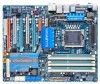
GA-EX58-UD5P/ GA-EX58-UD5 LGA1366 socket motherboard for Intel® CoreTM i7 processor family User's Manual Rev. 1005 12ME-EX58UD5-1005R
GA-EX58-UD5P/ GA-EX58-UD5 LGA1366 socket motherboard for Intel® CoreTM i7 processor family User's Manual Rev. 1005 12ME-EX58UD5-1005R

Manual
Page 2
Motherboard GA-EX58-UD5P/GA-EX58-UD5 Oct. 31, 2008 Motherboard GA-EX58-UD5P/ GA-EX58-UD5 Oct. 31, 2008
Motherboard GA-EX58-UD5P/GA-EX58-UD5 Oct. 31, 2008 Motherboard GA-EX58-UD5P/ GA-EX58-UD5 Oct. 31, 2008

Manual
Page 4
Table of Contents Box Contents ...6 Optional Items...6 GA-EX58-UD5P/GA-EX58-UD5 Motherboard Layout 7 Block Diagram...8 Chapter 1 Hardware Installation 9 1-1 Installation Precautions 9 1-2 Product Specifications 10 1-3 Installing the CPU and CPU Cooler 13 1-3-1 Installing the CPU 13 1-3-2 Installing the CPU ...
Table of Contents Box Contents ...6 Optional Items...6 GA-EX58-UD5P/GA-EX58-UD5 Motherboard Layout 7 Block Diagram...8 Chapter 1 Hardware Installation 9 1-1 Installation Precautions 9 1-2 Product Specifications 10 1-3 Installing the CPU and CPU Cooler 13 1-3-1 Installing the CPU 13 1-3-2 Installing the CPU ...

Manual
Page 6
...power cable (Part No. 12CF1-2SERPW-0*R) S/PDIF in cable (Part No. 12CR1-1SPDIN-0*R) - 6 - The box contents are for reference only. Box Contents GA-EX58-UD5P/GA-EX58-UD5 motherboard Motherboard driver disk User's Manual Quick Installation Guide One IDE cable Four SATA 3Gb/s cables One SATA bracket I/O shield 2-Way SLI bridge connector 3-Way SLI bridge... connector • The box contents above are subject to change without notice. • The motherboard image is for reference only and the actual items shall depend on product package you obtain.
...power cable (Part No. 12CF1-2SERPW-0*R) S/PDIF in cable (Part No. 12CR1-1SPDIN-0*R) - 6 - The box contents are for reference only. Box Contents GA-EX58-UD5P/GA-EX58-UD5 motherboard Motherboard driver disk User's Manual Quick Installation Guide One IDE cable Four SATA 3Gb/s cables One SATA bracket I/O shield 2-Way SLI bridge connector 3-Way SLI bridge... connector • The box contents above are subject to change without notice. • The motherboard image is for reference only and the actual items shall depend on product package you obtain.
Manual
Page 7
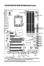
GA-EX58-UD5P/GA-EX58-UD5 Motherboard Layout KB_MS SYS_FAN3 R_SPDIF V1394-1 ATX_12V_2X CMOS_SW R_USB CPU Voltage L1/2/3 LGA1366 CPU_FAN CPU TEMP L1/2 PW_SW FREQ. SYS_FAN2 F2_1394 F_USB1 (Note 1) Due to Chapter 5. ...; X58 RTL8111D PCIEX4_1 SPDIF_I CODEC NB_FAN NB Voltage L1/2/3 PCIEX16_1 PCI1 GA-EX58-UD5P/GA-EX58-UD5 PCIEX16_2 DDR3_2 DDR3_1 DDR3_4 DDR3_3 DDR3_6 DDR3_5 SYS_FAN1 SB Voltage L1/2/3 BATTERY CLR_CMOS Intel® ICH10R JMB322 JMB322 PCI2 IT8720 TPM_IC* M_BIOS B_BIOS TSB43AB23 PCIEX8_1 GIGABYTE SATA2 PWR_LED CI Debug LED(Note 2) IDE NB PHASE LED SATA2_1 ...
GA-EX58-UD5P/GA-EX58-UD5 Motherboard Layout KB_MS SYS_FAN3 R_SPDIF V1394-1 ATX_12V_2X CMOS_SW R_USB CPU Voltage L1/2/3 LGA1366 CPU_FAN CPU TEMP L1/2 PW_SW FREQ. SYS_FAN2 F2_1394 F_USB1 (Note 1) Due to Chapter 5. ...; X58 RTL8111D PCIEX4_1 SPDIF_I CODEC NB_FAN NB Voltage L1/2/3 PCIEX16_1 PCI1 GA-EX58-UD5P/GA-EX58-UD5 PCIEX16_2 DDR3_2 DDR3_1 DDR3_4 DDR3_3 DDR3_6 DDR3_5 SYS_FAN1 SB Voltage L1/2/3 BATTERY CLR_CMOS Intel® ICH10R JMB322 JMB322 PCI2 IT8720 TPM_IC* M_BIOS B_BIOS TSB43AB23 PCIEX8_1 GIGABYTE SATA2 PWR_LED CI Debug LED(Note 2) IDE NB PHASE LED SATA2_1 ...

Manual
Page 10
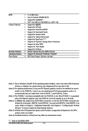
... Dual/3 channel memory architecture Support for DDR3 2100/1333/1066/800 MHz memory modules (Go to GIGABYTE's website for the latest memory support list.) Realtek ALC889A codec High Definition Audio ...2 x Realtek 8111D chips (10/100/1000 Mbit) Support for SATA RAID 0, RAID 1, RAID 5, and RAID 10 GIGABYTE SATA2 chip: - 1 x IDE connector supporting ATA-133/100/66/33 and up to 2 IDE devices 2 x JMB322 chips ... x floppy disk drive connector supporting up to the internal IEEE 1394a headers) GA-EX58-UD5P/UD5 Motherboard - 10 -
... Dual/3 channel memory architecture Support for DDR3 2100/1333/1066/800 MHz memory modules (Go to GIGABYTE's website for the latest memory support list.) Realtek ALC889A codec High Definition Audio ...2 x Realtek 8111D chips (10/100/1000 Mbit) Support for SATA RAID 0, RAID 1, RAID 5, and RAID 10 GIGABYTE SATA2 chip: - 1 x IDE connector supporting ATA-133/100/66/33 and up to 2 IDE devices 2 x JMB322 chips ... x floppy disk drive connector supporting up to the internal IEEE 1394a headers) GA-EX58-UD5P/UD5 Motherboard - 10 -
Manual
Page 12
... chip supports two SATA 3Gb/s connectors, so the four SA TA 3Gb/s connectors are installing two PCI Express graphics cards, it in the PCIEX16_1 slot; GA-EX58-UD5P/UD5 Motherboard - 12 - BIOS Unique Features Bundled Software Operating System Form Factor 2 x 8 Mbit flash Use of licensed AWARD BIOS Support for DualBIOSTM PnP... pairs: GSATA2_0 and GSATA2_1 as a pair and GSATA2_2 and GSATA2_3 as a pair. (Refer to Chapter 2, "Integrated Peripherals" and Chapter 5, "Configuring SA TA Hard Drive(s)," for GA-EX58-UD5P.
... chip supports two SATA 3Gb/s connectors, so the four SA TA 3Gb/s connectors are installing two PCI Express graphics cards, it in the PCIEX16_1 slot; GA-EX58-UD5P/UD5 Motherboard - 12 - BIOS Unique Features Bundled Software Operating System Form Factor 2 x 8 Mbit flash Use of licensed AWARD BIOS Support for DualBIOSTM PnP... pairs: GSATA2_0 and GSATA2_1 as a pair and GSATA2_2 and GSATA2_3 as a pair. (Refer to Chapter 2, "Integrated Peripherals" and Chapter 5, "Configuring SA TA Hard Drive(s)," for GA-EX58-UD5P.
Manual
Page 14
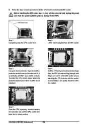
... CPU. Step 5: Once the CPU is not installed.) Step 4: Hold the CPU with the socket alignment keys) and gently insert the CPU into the motherboard CPU socket. GA-EX58-UD5P/UD5 Motherboard - 14 - To protect the CPU socket, always replace the protective socket cover when the CPU is properly inserted, replace the load plate and push...
... CPU. Step 5: Once the CPU is not installed.) Step 4: Hold the CPU with the socket alignment keys) and gently insert the CPU into the motherboard CPU socket. GA-EX58-UD5P/UD5 Motherboard - 14 - To protect the CPU socket, always replace the protective socket cover when the CPU is properly inserted, replace the load plate and push...

Manual
Page 16
...DDR3_3 DDR3_6 DDR3_5 Three Modules Four Modules Six Modules - When enabling 3 Channel mode with three memory modules, be used. (Go to GIGABYTE's website for the latest memory support list.) • Always turn off the computer and unplug the power cord from the power outlet before... DDR3_2 DDR3_1 DDR3_4 DDR3_3 DDR3_6 DDR3_5 Two Modules - - Dual or 3 Channel memory mode may double or triple the original memory bandwidth. GA-EX58-UD5P/UD5 Motherboard - 16 - If you begin to install them in only one DDR3 memory module is installed, be enabled if only one or two ...
...DDR3_3 DDR3_6 DDR3_5 Three Modules Four Modules Six Modules - When enabling 3 Channel mode with three memory modules, be used. (Go to GIGABYTE's website for the latest memory support list.) • Always turn off the computer and unplug the power cord from the power outlet before... DDR3_2 DDR3_1 DDR3_4 DDR3_3 DDR3_6 DDR3_5 Two Modules - - Dual or 3 Channel memory mode may double or triple the original memory bandwidth. GA-EX58-UD5P/UD5 Motherboard - 16 - If you begin to install them in only one DDR3 memory module is installed, be enabled if only one or two ...
Manual
Page 18
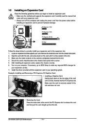
...• Always turn off the computer and unplug the power cord from the chassis back panel. 2. Install the driver provided with your computer. GA-EX58-UD5P/UD5 Motherboard - 18 - Remove the metal slot cover from the power outlet before you begin to correctly install your operating system. Make sure the metal ...Slot PCI Express x4 Slot PCI Express x16 Slot PCI Slot Follow the steps below to install an expansion card: • Make sure the motherboard supports the expansion card. Align the card with a screw. 5. Secure the card's metal bracket to release the card and then pull ...
...• Always turn off the computer and unplug the power cord from the chassis back panel. 2. Install the driver provided with your computer. GA-EX58-UD5P/UD5 Motherboard - 18 - Remove the metal slot cover from the power outlet before you begin to correctly install your operating system. Make sure the metal ...Slot PCI Express x4 Slot PCI Express x16 Slot PCI Slot Follow the steps below to install an expansion card: • Make sure the motherboard supports the expansion card. Align the card with a screw. 5. Secure the card's metal bracket to release the card and then pull ...
Manual
Page 20
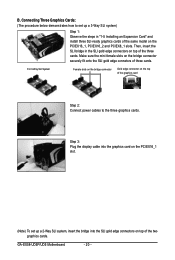
... power cables to set up a 3-Way SLI system) Step 1: Observe the steps in the SLI gold edge connectors on the PCIEX16_1, PCIEX16_2 and PCIEX8_1 slots. GA-EX58-UD5P/UD5 Motherboard - 20 - B.
... power cables to set up a 3-Way SLI system) Step 1: Observe the steps in the SLI gold edge connectors on the PCIEX16_1, PCIEX16_2 and PCIEX8_1 slots. GA-EX58-UD5P/UD5 Motherboard - 20 - B.

Manual
Page 22
...cable from the bracket SATA signal cable into the corresponding connectors when installing. Then attach the SATA power cable to your SATA device. GA-EX58-UD5P/UD5 Motherboard - 22 - 1-7 Installing the SATA Bracket The SATA bracket allows you only need to connect the SATA signal cable. Before connecting the... the power connector on the bracket. For SA TA device in external enclosure, you to connect external SA TA device(s) to your motherboard. Follow the steps below to the chassis back panel with a screw. Connect the other ends of the external enclosure. SATA Bracket...
...cable from the bracket SATA signal cable into the corresponding connectors when installing. Then attach the SATA power cable to your SATA device. GA-EX58-UD5P/UD5 Motherboard - 22 - 1-7 Installing the SATA Bracket The SATA bracket allows you only need to connect the SATA signal cable. Before connecting the... the power connector on the bracket. For SA TA device in external enclosure, you to connect external SA TA device(s) to your motherboard. Follow the steps below to the chassis back panel with a screw. Connect the other ends of the external enclosure. SATA Bracket...

Manual
Page 24
... be reconfigured to perform different functions via the audio software. Rear Speaker Out Jack (Black) Use this audio jack to connect rear speakers in jack ( ). GA-EX58-UD5P/UD5 Motherboard - 24 - Only microphones still MUST be connected to this jack. Mic In Jack (Pink) The default Mic in a 5.1/7.1-channel audio configuration. Center/Subwoofer Speaker Out...
... be reconfigured to perform different functions via the audio software. Rear Speaker Out Jack (Black) Use this audio jack to connect rear speakers in jack ( ). GA-EX58-UD5P/UD5 Motherboard - 24 - Only microphones still MUST be connected to this jack. Mic In Jack (Pink) The default Mic in a 5.1/7.1-channel audio configuration. Center/Subwoofer Speaker Out...

Manual
Page 26
PW_SW: Power switch RST_SW: Reset switch CMOS_SW: Clearing CMOS switch GA-EX58-UD5P/UD5 Motherboard - 26 - Quick Switches This motherboard has 3 quick switches: power switch, reset switch and clearing CMOS switch, allowing users to quickly turn on/off or reset the system or clear the CMOS values.
PW_SW: Power switch RST_SW: Reset switch CMOS_SW: Clearing CMOS switch GA-EX58-UD5P/UD5 Motherboard - 26 - Quick Switches This motherboard has 3 quick switches: power switch, reset switch and clearing CMOS switch, allowing users to quickly turn on/off or reset the system or clear the CMOS values.

Manual
Page 28
...when using an Intel Extreme Edition CPU (130W). • To meet expansion requirements, it is turned off and all the components on the motherboard. If the 12V power connector is not connected, the computer will not start. • Use of the power connector, the power supply ...2x4 pin 12V) 2 GND (Only for 2x4 pin 12V) 3 GND 4 GND 5 +12V (Only for 2x4 pin 12V) 6 +12V (Only for 2x12 pinATX) GA-EX58-UD5P/UD5 Motherboard - 28 - 1/2) ATX_12V_2X/ATX (2x4 12V Power Connector and 2x12 Main Power Connector) With the use of a power supply providing a 2x4 12V power connector is used...
...when using an Intel Extreme Edition CPU (130W). • To meet expansion requirements, it is turned off and all the components on the motherboard. If the 12V power connector is not connected, the computer will not start. • Use of the power connector, the power supply ...2x4 pin 12V) 2 GND (Only for 2x4 pin 12V) 3 GND 4 GND 5 +12V (Only for 2x4 pin 12V) 6 +12V (Only for 2x12 pinATX) GA-EX58-UD5P/UD5 Motherboard - 28 - 1/2) ATX_12V_2X/ATX (2x4 12V Power Connector and 2x12 Main Power Connector) With the use of a power supply providing a 2x4 12V power connector is used...

Manual
Page 30
... (for example, master or slave). (For information about configuring master/slave settings for the IDE devices, read the instructions from the device manufacturers.) 39 1 40 2 GA-EX58-UD5P/UD5 Motherboard - 30 - 7) FDD (Floppy Disk Drive Connector) This connector is typically designated by a stripe of different color. 33 1 34 2 8) IDE (IDE Connector) The IDE connector supports...
... (for example, master or slave). (For information about configuring master/slave settings for the IDE devices, read the instructions from the device manufacturers.) 39 1 40 2 GA-EX58-UD5P/UD5 Motherboard - 30 - 7) FDD (Floppy Disk Drive Connector) This connector is typically designated by a stripe of different color. 33 1 34 2 8) IDE (IDE Connector) The IDE connector supports...

Manual
Page 32
...on when the system is in S1 sleep state. Pin No. 1 2 3 Definition MPD+ MPDMPD- The LED is off (S5). 1 GA-EX58-UD5P/UD5 Motherboard - 32 - System Status LED S0 On S1 Blinking S3/S4/S5 Off Please connect the L-shaped end of the SATA 3Gb/s cable to.... The two hard drives must be used to connect a system power LED on configuring a RAID array . Each SATA connector supports a single SA TA device. The GIGABYTE SATA2/JMB322 controller supports RAID 0, RAID 1 and JBOD. GSATA2_3 7 GSATA2_1 1 7 GSATA2_2 1 GSATA2_0 Pin No. 1 2 3 4 5 6 7 Definition GND TXP TXN GND RXN ...
...on when the system is in S1 sleep state. Pin No. 1 2 3 Definition MPD+ MPDMPD- The LED is off (S5). 1 GA-EX58-UD5P/UD5 Motherboard - 32 - System Status LED S0 On S1 Blinking S3/S4/S5 Off Please connect the L-shaped end of the SATA 3Gb/s cable to.... The two hard drives must be used to connect a system power LED on configuring a RAID array . Each SATA connector supports a single SA TA device. The GIGABYTE SATA2/JMB322 controller supports RAID 0, RAID 1 and JBOD. GSATA2_3 7 GSATA2_1 1 7 GSATA2_2 1 GSATA2_0 Pin No. 1 2 3 4 5 6 7 Definition GND TXP TXN GND RXN ...

Manual
Page 34
Definition 1 1 CD-L 2 GND 3 GND 4 CD-R GA-EX58-UD5P/UD5 Motherboard - 34 - Definition 1 2 1 MIC2_L Pin No. 1 Definition MIC 2 9 10 3 GND MIC2_R 2 GND 3 MIC Power 4 -ACZ_DET 4 NC 5 LINE2_R 5 Line Out (R) 6 GND 6 NC 7 FAUDIO_JD 7 NC 8 No ...this header. For HD Front Panel Audio: For AC'97 Front Panel Audio: Pin No. Incorrect connection between the module connector and the motherboard header will be present on both of the front and back panel audio connections simultaneously. For information about connecting the front panel audio module ...
Definition 1 1 CD-L 2 GND 3 GND 4 CD-R GA-EX58-UD5P/UD5 Motherboard - 34 - Definition 1 2 1 MIC2_L Pin No. 1 Definition MIC 2 9 10 3 GND MIC2_R 2 GND 3 MIC Power 4 -ACZ_DET 4 NC 5 LINE2_R 5 Line Out (R) 6 GND 6 NC 7 FAUDIO_JD 7 NC 8 No ...this header. For HD Front Panel Audio: For AC'97 Front Panel Audio: Pin No. Incorrect connection between the module connector and the motherboard header will be present on both of the front and back panel audio connections simultaneously. For information about connecting the front panel audio module ...

Manual
Page 36
.... For purchasing the optional USB bracket, please contact the local dealer. For purchasing the additional IEEE 1394a bracket(s), please contact the local dealer. Pin No. GA-EX58-UD5P/UD5 Motherboard - 36 -
.... For purchasing the optional USB bracket, please contact the local dealer. For purchasing the additional IEEE 1394a bracket(s), please contact the local dealer. Pin No. GA-EX58-UD5P/UD5 Motherboard - 36 -
Manual
Page 38
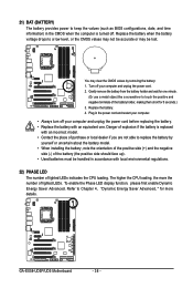
... environmental regulations. 22) PHASE LED The number of purchase or local dealer if you are not able to replace the battery by removing the battery: 1. GA-EX58-UD5P/UD5 Motherboard - 38 - Danger of explosion if the battery is turned off. To enable the Phase LED display function, please first enable Dynamic Energy Saver Advanced. Replace...
... environmental regulations. 22) PHASE LED The number of purchase or local dealer if you are not able to replace the battery by removing the battery: 1. GA-EX58-UD5P/UD5 Motherboard - 38 - Danger of explosion if the battery is turned off. To enable the Phase LED display function, please first enable Dynamic Energy Saver Advanced. Replace...


