Manual
Page 1
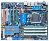
GA-EX58-UD5P/ GA-EX58-UD5 LGA1366 socket motherboard for Intel® CoreTM i7 processor family User's Manual Rev. 1005 12ME-EX58UD5-1005R
GA-EX58-UD5P/ GA-EX58-UD5 LGA1366 socket motherboard for Intel® CoreTM i7 processor family User's Manual Rev. 1005 12ME-EX58UD5-1005R
Manual
Page 3
...\Motherboard\Technology Guide page on how to their respective owners. Disclaimer Information in this product, GIGABYTE provides the following types of documentations: For quick set-up of GIGABYTE. Documentation Classifications In order to assist in this manual may be made by copyright laws and is 1.0. The trademarks mentioned in the use of...
...\Motherboard\Technology Guide page on how to their respective owners. Disclaimer Information in this product, GIGABYTE provides the following types of documentations: For quick set-up of GIGABYTE. Documentation Classifications In order to assist in this manual may be made by copyright laws and is 1.0. The trademarks mentioned in the use of...
Manual
Page 5
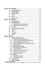
... 3 Drivers Installation 73 3-1 Installing Chipset Drivers 73 3-2 Application Software 74 3-3 Technical Manuals 74 3-4 Contact ...75 3-5 System ...75 3-6 Download Center 76 Chapter 4 Unique ...4-8 Teaming ...90 Chapter 5 Appendix ...91 5-1 Configuring SATA Hard Drive(s 91 5-1-1 Configuring Intel ICH10R SATA Controllers 91 5-1-2 Configuring GIGABYTE SATA2/JMB322 SATA Controller 97 5-1-3 Making a SATA RAID/AHCI Driver Diskette 99 5-1-4 Installing the SATA RAID/AHCI Driver and Operating System... 116 5-4 POST Error Code 118 5-5 Regulatory Statements 122 "*" Only for GA-EX58-UD5P. - 5 -
... 3 Drivers Installation 73 3-1 Installing Chipset Drivers 73 3-2 Application Software 74 3-3 Technical Manuals 74 3-4 Contact ...75 3-5 System ...75 3-6 Download Center 76 Chapter 4 Unique ...4-8 Teaming ...90 Chapter 5 Appendix ...91 5-1 Configuring SATA Hard Drive(s 91 5-1-1 Configuring Intel ICH10R SATA Controllers 91 5-1-2 Configuring GIGABYTE SATA2/JMB322 SATA Controller 97 5-1-3 Making a SATA RAID/AHCI Driver Diskette 99 5-1-4 Installing the SATA RAID/AHCI Driver and Operating System... 116 5-4 POST Error Code 118 5-5 Regulatory Statements 122 "*" Only for GA-EX58-UD5P. - 5 -

Manual
Page 6
The box contents are for reference only. Box Contents GA-EX58-UD5P/GA-EX58-UD5 motherboard Motherboard driver disk User's Manual Quick Installation Guide One IDE cable Four SATA 3Gb/s cables One SATA bracket I/O shield 2-Way SLI bridge connector 3-Way SLI bridge connector • The box ...
The box contents are for reference only. Box Contents GA-EX58-UD5P/GA-EX58-UD5 motherboard Motherboard driver disk User's Manual Quick Installation Guide One IDE cable Four SATA 3Gb/s cables One SATA bracket I/O shield 2-Way SLI bridge connector 3-Way SLI bridge connector • The box ...
Manual
Page 9
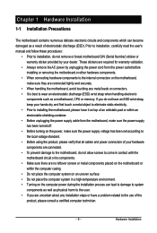
...; Before turning on the computer power during the installation process can become damaged as a motherboard, CPU or memory. Prior to installation, carefully read the user's manual and follow these procedures: • Prior to installation, do not allow screws to wear an electrostatic discharge (ESD) wrist strap when handling electronic components such...
...; Before turning on the computer power during the installation process can become damaged as a motherboard, CPU or memory. Prior to installation, carefully read the user's manual and follow these procedures: • Prior to installation, do not allow screws to wear an electrostatic discharge (ESD) wrist strap when handling electronic components such...
Manual
Page 15
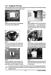
... pins through the pin holes on the motherboard. Check that the Male and Female push pins are joined closely. (Refer to your CPU cooler installation manual for instructions on installing the cooler.) Step 5: After the installation, check the back of the installed CPU.
... pins through the pin holes on the motherboard. Check that the Male and Female push pins are joined closely. (Refer to your CPU cooler installation manual for instructions on installing the cooler.) Step 5: After the installation, check the back of the installed CPU.
Manual
Page 18
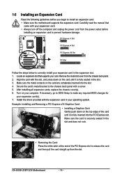
...rock. • Removing the Card: Press the white latch at the end of the card until it is fully seated in the slot. 3. GA-EX58-UD5P/UD5 Motherboard - 18 - Secure the card's metal bracket to correctly install your expansion card in your expansion card. • Always turn off the ...on your card. Remove the metal slot cover from the slot. After installing all expansion cards, replace the chassis cover(s). 6. Carefully read the manual that supports your computer. Locate an expansion slot that came with the expansion card in the expansion slot. 1. Turn on the card are ...
...rock. • Removing the Card: Press the white latch at the end of the card until it is fully seated in the slot. 3. GA-EX58-UD5P/UD5 Motherboard - 18 - Secure the card's metal bracket to correctly install your expansion card in your expansion card. • Always turn off the ...on your card. Remove the metal slot cover from the slot. After installing all expansion cards, replace the chassis cover(s). 6. Carefully read the manual that supports your computer. Locate an expansion slot that came with the expansion card in the expansion slot. 1. Turn on the card are ...

Manual
Page 21
... - Configuring the Graphics Card Driver: C-1 To enable SLI function For 2-Way/3-Way SLI: After installing graphics card driver in the operating system, go to the manual that came with your graphics cards for enabling SLI/CrossFireX technology may slightly differ by graphics cards. Ensure SLI configuration and Physx are enabled. For...
... - Configuring the Graphics Card Driver: C-1 To enable SLI function For 2-Way/3-Way SLI: After installing graphics card driver in the operating system, go to the manual that came with your graphics cards for enabling SLI/CrossFireX technology may slightly differ by graphics cards. Ensure SLI configuration and Physx are enabled. For...

Manual
Page 35
...) for your motherboard to certain expansion cards like graphics cards and sound cards. For information about connecting the S/PDIF digital audio cable, carefully read the manual for digital audio output from your expansion card. Pin No.
...) for your motherboard to certain expansion cards like graphics cards and sound cards. For information about connecting the S/PDIF digital audio cable, carefully read the manual for digital audio output from your expansion card. Pin No.
Manual
Page 37
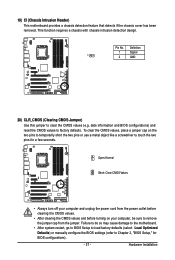
... do so may cause damage to the motherboard. • After system restart, go to BIOS Setup to load factory defaults (select Load Optimized Defaults) or manually configure the BIOS settings (refer to factory defaults. 19) CI (Chassis Intrusion Header) This motherboard provides a chassis detection feature that detects if the chassis cover...
... do so may cause damage to the motherboard. • After system restart, go to BIOS Setup to load factory defaults (select Load Optimized Defaults) or manually configure the BIOS settings (refer to factory defaults. 19) CI (Chassis Intrusion Header) This motherboard provides a chassis detection feature that detects if the chassis cover...

Manual
Page 48
... standard 100 MHz. (Default: Auto) C.I.A.2 CPU Intelligent Accelerator 2 (C.I.A.2) is from 100 MHz to manually set the CPU base clock. Note: System stability varies, depending on your CPU. Turbo Increases CPU ...manually set the PCIe clock frequency. Sports Increases CPU frequency by 9% or 1 1% depending on CPU loading. The adjustable range is designed to automatically adjust CPU computing power to 150 MHz. As stability is from 90 MHz to maximize system performance. Racing Increases CPU frequency by 7% or 9% depending on CPU loading. GA-EX58-UD5P/UD5...
... standard 100 MHz. (Default: Auto) C.I.A.2 CPU Intelligent Accelerator 2 (C.I.A.2) is from 100 MHz to manually set the CPU base clock. Note: System stability varies, depending on your CPU. Turbo Increases CPU ...manually set the PCIe clock frequency. Sports Increases CPU frequency by 9% or 1 1% depending on CPU loading. The adjustable range is designed to automatically adjust CPU computing power to 150 MHz. As stability is from 90 MHz to maximize system performance. Racing Increases CPU frequency by 7% or 9% depending on CPU loading. GA-EX58-UD5P/UD5...

Manual
Page 50
... Profile (X.M.P.) is set the system memory multiplier. When Extreme Memory Profile (X.M.P.) is set to Disabled, this item will display as 1.5V. GA-EX58-UD5P/UD5 Motherboard - 50 - Auto sets memory multiplier according to memory SPD data. (Default: Auto) Memory Frequency (Mhz) The first memory frequency ... is the normal operating frequency of the memory being used ; tRP Options are : Auto (default), 1~15. DRAM Timing Selectable (SPD) Manual allows all DRAM Timing items below to the BCLK Frequency (Mhz) and System Memory Multiplier settings. ESC: Exit F1: General Help F7: ...
... Profile (X.M.P.) is set the system memory multiplier. When Extreme Memory Profile (X.M.P.) is set to Disabled, this item will display as 1.5V. GA-EX58-UD5P/UD5 Motherboard - 50 - Auto sets memory multiplier according to memory SPD data. (Default: Auto) Memory Frequency (Mhz) The first memory frequency ... is the normal operating frequency of the memory being used ; tRP Options are : Auto (default), 1~15. DRAM Timing Selectable (SPD) Manual allows all DRAM Timing items below to the BCLK Frequency (Mhz) and System Memory Multiplier settings. ESC: Exit F1: General Help F7: ...

Manual
Page 56
...amount of memory installed on this channel. Drive A Allows you wish to enter the parameters manually, refer to the information on the hard drive. Base Memory Also called conventional memory. GA-EX58-UD5P/UD5 Motherboard - 56 - IDE Channel 2/3 Master, IDE Channel 4/5 Master/Slave IDE Auto-...default), Drive A. If you to selects the type of floppy disk drive installed in your system. Floppy 3 Mode Support Allows you to manually enter the specifications of the hard drive when the hard drive access mode is 3-mode floppy disk drive, a Japanese standard floppy disk ...
...amount of memory installed on this channel. Drive A Allows you wish to enter the parameters manually, refer to the information on the hard drive. Base Memory Also called conventional memory. GA-EX58-UD5P/UD5 Motherboard - 56 - IDE Channel 2/3 Master, IDE Channel 4/5 Master/Slave IDE Auto-...default), Drive A. If you to selects the type of floppy disk drive installed in your system. Floppy 3 Mode Support Allows you to manually enter the specifications of the hard drive when the hard drive access mode is 3-mode floppy disk drive, a Japanese standard floppy disk ...

Manual
Page 73
... automatically scan your system and then list all the recommended drivers. The driver Autorun screen is installing the drivers. Or click Install Single Items to manually select the drivers you wish to install.
... automatically scan your system and then list all the recommended drivers. The driver Autorun screen is installing the drivers. Or click Install Single Items to manually select the drivers you wish to install.

Manual
Page 74
You can click the Install button on the right of an item to install it. 3-3 Technical Manuals This page provides GIGABYTE's application guides, content descriptions for this driver disk, and the motherboard manuals. 3-2 Application Software This page displays all the utilities and applications that GIGABYTE develops and some free software. GA-EX58-UD5P/UD5 Motherboard - 74 -
You can click the Install button on the right of an item to install it. 3-3 Technical Manuals This page provides GIGABYTE's application guides, content descriptions for this driver disk, and the motherboard manuals. 3-2 Application Software This page displays all the utilities and applications that GIGABYTE develops and some free software. GA-EX58-UD5P/UD5 Motherboard - 74 -

Manual
Page 75
3-4 Contact Click the URL on this page to link to check the contact information for GIGABYTE Taiwan headquarter or worldwide branch of fices. 3-5 System This page provides the basic system information. - 75 - Drivers Installation Or read the last page of th is manual to the GIGABYTE Web site.
3-4 Contact Click the URL on this page to link to check the contact information for GIGABYTE Taiwan headquarter or worldwide branch of fices. 3-5 System This page provides the basic system information. - 75 - Drivers Installation Or read the last page of th is manual to the GIGABYTE Web site.

Manual
Page 80
...either pressing the key during the POST to enter operating systems like MS-DOS or Window first. GA-EX58-UD5P/UD5 Motherboard - 80 - From GIGABYTE's website, download the latest compressed BIOS update file that support DualBIOS have two BIOS onboard, a ...GIGABYTE motherboards provide two unique BIOS update tools, Q-Flash TM and @BIOS .TM GIGABYTE Q-Flash and @BIOS are easy-to-use F AT32/16/12 file system. 3. Additionally, this motherboard features the DualBIOS TM design, which enhances protection for the safety and stability of system safety, users cannot update the backup BIOS manually...
...either pressing the key during the POST to enter operating systems like MS-DOS or Window first. GA-EX58-UD5P/UD5 Motherboard - 80 - From GIGABYTE's website, download the latest compressed BIOS update file that support DualBIOS have two BIOS onboard, a ...GIGABYTE motherboards provide two unique BIOS update tools, Q-Flash TM and @BIOS .TM GIGABYTE Q-Flash and @BIOS are easy-to-use F AT32/16/12 file system. 3. Additionally, this motherboard features the DualBIOS TM design, which enhances protection for the safety and stability of system safety, users cannot update the backup BIOS manually...

Manual
Page 83
...not to boot. - 83 - During the BIOS update process, ensure the Internet connection is not present on the @BIOS server site, please manually download the BIOS update file from File, then select the location where you save the current BIOS file. 4. Follow the on - If the... file obtained from the Internet or through other source. Using @BIOS: 1. Updating the BIOS with the @BIOS Utility A. B. Do not use the G.O.M. (GIGABYTE Online Management) function when using @BIOS. 4. tions in a corrupted BIOS or a system that the BIOS file to complete. Before You Begin: 1. After ...
...not to boot. - 83 - During the BIOS update process, ensure the Internet connection is not present on the @BIOS server site, please manually download the BIOS update file from File, then select the location where you save the current BIOS file. 4. Follow the on - If the... file obtained from the Internet or through other source. Using @BIOS: 1. Updating the BIOS with the @BIOS Utility A. B. Do not use the G.O.M. (GIGABYTE Online Management) function when using @BIOS. 4. tions in a corrupted BIOS or a system that the BIOS file to complete. Before You Begin: 1. After ...

Manual
Page 90
... tolerance on this motherboard allows two single connections to access the utility. Step 2: Click the Start icon . Restart your network switch or router device manual for installation. GA-EX58-UD5P/UD5 Motherboard - 90 - Step 3: Select the two adapters and set up the Teaming mode based on your hub's specifications. Point to All Programs, Realtek...
... tolerance on this motherboard allows two single connections to access the utility. Step 2: Click the Start icon . Restart your network switch or router device manual for installation. GA-EX58-UD5P/UD5 Motherboard - 90 - Step 3: Select the two adapters and set up the Teaming mode based on your hub's specifications. Point to All Programs, Realtek...

Manual
Page 104
...drive to add into the array to be rebuilt within the operating system. []-Select [ESC]-Exit [ENTER]-Select Menu GA-EX58-UD5P/UD5 Motherboard - 104 - If you do not enable automatic rebuild on this stage, you enter the RAID Configuration Utility. Rebuilding an ...): [ DISK/VOLUME INFORMATION ] RAID VolPumoretsD:rive Model None defin1ed. Rebuilding applies only to enter the RAID Configuration Utility. Reset Disks to manually rebuild the array in the op4.eraEtxinitg system. Exit RAID Volumes : ID Name 0 gbb [ DISK/VOLUME INFORMATION ] Level RAID1(Mirror)...
...drive to add into the array to be rebuilt within the operating system. []-Select [ESC]-Exit [ENTER]-Select Menu GA-EX58-UD5P/UD5 Motherboard - 104 - If you do not enable automatic rebuild on this stage, you enter the RAID Configuration Utility. Rebuilding an ...): [ DISK/VOLUME INFORMATION ] RAID VolPumoretsD:rive Model None defin1ed. Rebuilding applies only to enter the RAID Configuration Utility. Reset Disks to manually rebuild the array in the op4.eraEtxinitg system. Exit RAID Volumes : ID Name 0 gbb [ DISK/VOLUME INFORMATION ] Level RAID1(Mirror)...


