
Manual
Page 4
Table of Contents Box Contents ...6 Optional Items...6 GA-EX58-UD5P/GA-EX58-UD5 Motherboard Layout 7 Block Diagram...8 Chapter 1 Hardware Installation 9 1-1 Installation Precautions 9 1-2 Product Specifications 10 1-3 Installing the CPU and CPU Cooler 13 1-3-1 Installing... 18 1-6 Setup of NVIDIA SLI (Scalable Link Interface)/ATI CrossFireX Configuration. 19 1-7 Installing the SATA Bracket 22 1-8 Back Panel Connectors 23 1-9 Onboard LEDs and Switches 25 1-10 Internal Connectors 27 Chapter 2 BIOS Setup 41 2-1 Startup Screen 42 2-2 The Main Menu 43 2-3 MB Intelligent Tweaker(M.I.T 45 ...
Table of Contents Box Contents ...6 Optional Items...6 GA-EX58-UD5P/GA-EX58-UD5 Motherboard Layout 7 Block Diagram...8 Chapter 1 Hardware Installation 9 1-1 Installation Precautions 9 1-2 Product Specifications 10 1-3 Installing the CPU and CPU Cooler 13 1-3-1 Installing... 18 1-6 Setup of NVIDIA SLI (Scalable Link Interface)/ATI CrossFireX Configuration. 19 1-7 Installing the SATA Bracket 22 1-8 Back Panel Connectors 23 1-9 Onboard LEDs and Switches 25 1-10 Internal Connectors 27 Chapter 2 BIOS Setup 41 2-1 Startup Screen 42 2-2 The Main Menu 43 2-3 MB Intelligent Tweaker(M.I.T 45 ...
Manual
Page 7
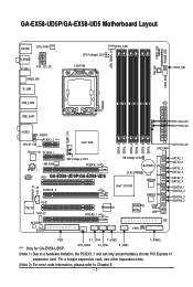
... SPDIF_I CODEC NB_FAN NB Voltage L1/2/3 PCIEX16_1 PCI1 GA-EX58-UD5P/GA-EX58-UD5 PCIEX16_2 DDR3_2 DDR3_1 DDR3_4 DDR3_3 DDR3_6 DDR3_5 SYS_FAN1 SB Voltage L1/2/3 BATTERY CLR_CMOS Intel® ICH10R JMB322 JMB322 PCI2 IT8720 TPM_IC* M_BIOS B_BIOS TSB43AB23 PCIEX8_1 GIGABYTE SATA2 PWR_LED CI Debug LED(Note 2) IDE NB PHASE LED SATA2_1 SATA2_0 SATA2_3 SATA2_2 SATA2_5 SATA2_4 GSATA2_1 GSATA2_0...
... SPDIF_I CODEC NB_FAN NB Voltage L1/2/3 PCIEX16_1 PCI1 GA-EX58-UD5P/GA-EX58-UD5 PCIEX16_2 DDR3_2 DDR3_1 DDR3_4 DDR3_3 DDR3_6 DDR3_5 SYS_FAN1 SB Voltage L1/2/3 BATTERY CLR_CMOS Intel® ICH10R JMB322 JMB322 PCI2 IT8720 TPM_IC* M_BIOS B_BIOS TSB43AB23 PCIEX8_1 GIGABYTE SATA2 PWR_LED CI Debug LED(Note 2) IDE NB PHASE LED SATA2_1 SATA2_0 SATA2_3 SATA2_2 SATA2_5 SATA2_4 GSATA2_1 GSATA2_0...
Manual
Page 11
... header 1 x CD In connector 1 x S/PDIF In header 1 x S/PDIF Out header Back Panel Connectors 2 x USB 2.0/1.1 headers 2 x IEEE 1394a headers 1 x power LED header 1 x chassis intrusion header 1 x power switch 1 x reset switch 1 x PS/2 keyboard port 1 x PS/2 mouse port 1 x coaxial S/PDIF Out connector ...
... header 1 x CD In connector 1 x S/PDIF In header 1 x S/PDIF Out header Back Panel Connectors 2 x USB 2.0/1.1 headers 2 x IEEE 1394a headers 1 x power LED header 1 x chassis intrusion header 1 x power switch 1 x reset switch 1 x PS/2 keyboard port 1 x PS/2 mouse port 1 x coaxial S/PDIF Out connector ...

Manual
Page 23
... specification. Use this port for USB devices such as an USB keyboard/mouse, USB printer, USB flash drive and etc. Connection/ Speed LED Activity LED LAN Port Connection/Speed LED: State Description Orange 1 Gbps data rate Green 100 Mbps data rate Off 10 Mbps data rate Activity...) to clear CMOS values. Before using this feature, ensure that supports digital optical audio. The following describes the states of the LAN port LEDs. RJ-45 LAN Port The Gigabit Ethernet LAN port provides Internet connection at up to an external audio system that your audio system provides a...
... specification. Use this port for USB devices such as an USB keyboard/mouse, USB printer, USB flash drive and etc. Connection/ Speed LED Activity LED LAN Port Connection/Speed LED: State Description Orange 1 Gbps data rate Green 100 Mbps data rate Off 10 Mbps data rate Activity...) to clear CMOS values. Before using this feature, ensure that supports digital optical audio. The following describes the states of the LAN port LEDs. RJ-45 LAN Port The Gigabit Ethernet LAN port provides Internet connection at up to an external audio system that your audio system provides a...

Manual
Page 25
...25 - CPU (FREQUENCY LED) Off: Normal condition F_LED1~F_LED5 : Blue Temperature Indicator LEDs The two sets of temperature indicator LEDs indicate the temperature level of lighted LEDs. Hardware Installation 1-9 Onboard LEDs and Switches Overvoltage LEDs This motherboard contains 4 sets of overvoltage LEDs which level the CPU is...: Normal condition L1: Level 1 (Slight, green) L2: Level 2 (Moderate, yellow) L3: Level 3 (High, red) Overclock LEDs The onboard CPU overclock LEDs indicate on which indicate the overvoltage level of the CPU, memory, North Bridge, and South Bridge. The...
...25 - CPU (FREQUENCY LED) Off: Normal condition F_LED1~F_LED5 : Blue Temperature Indicator LEDs The two sets of temperature indicator LEDs indicate the temperature level of lighted LEDs. Hardware Installation 1-9 Onboard LEDs and Switches Overvoltage LEDs This motherboard contains 4 sets of overvoltage LEDs which level the CPU is...: Normal condition L1: Level 1 (Slight, green) L2: Level 2 (Moderate, yellow) L3: Level 3 (High, red) Overclock LEDs The onboard CPU overclock LEDs indicate on which indicate the overvoltage level of the CPU, memory, North Bridge, and South Bridge. The...

Manual
Page 27
... 13) F_AUDIO 14) CD_IN 15) SPDIF_I 16) SPDIF_O 17) F_USB1/F_USB2 18) F1_1394/F2_1394 19) CI 20) CLR_CMOS 21) BAT 22) PHASE_LED 23) NB PHASE LED 24) DDR PHASE LED Read the following guidelines before turning on the motherboard. - 27 -
... 13) F_AUDIO 14) CD_IN 15) SPDIF_I 16) SPDIF_O 17) F_USB1/F_USB2 18) F1_1394/F2_1394 19) CI 20) CLR_CMOS 21) BAT 22) PHASE_LED 23) NB PHASE LED 24) DDR PHASE LED Read the following guidelines before turning on the motherboard. - 27 -

Manual
Page 32
... S1 sleep state. The GIGABYTE SATA2/JMB322 controller supports RAID 0, RAID 1 and JBOD. 10) GSATA2_0/1/2/3 (SATA 3Gb/s Connectors, Controlled by GIGABYTE SATA2/JMB322) The SATA connectors conform to Chapter 2, "Integrated Peripherals" and Chapter 5, "Configuring SATA Hard Drive(s)," for instructions on configuring a RAID array . The LED is off (S5). 1 GA-EX58-UD5P/UD5 Motherboard - 32 - Pin No...
... S1 sleep state. The GIGABYTE SATA2/JMB322 controller supports RAID 0, RAID 1 and JBOD. 10) GSATA2_0/1/2/3 (SATA 3Gb/s Connectors, Controlled by GIGABYTE SATA2/JMB322) The SATA connectors conform to Chapter 2, "Integrated Peripherals" and Chapter 5, "Configuring SATA Hard Drive(s)," for instructions on configuring a RAID array . The LED is off (S5). 1 GA-EX58-UD5P/UD5 Motherboard - 32 - Pin No...
Manual
Page 33
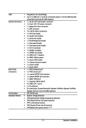
... assignments and the pin assignments are matched correctly. - 33 - Note the positive and negative pins before connecting the cables. Message/Power/ Power Sleep LED Switch Speaker MSG+ MSG- You may differ by issuing a beep code. Refer to Chapter 5, "Troubleshooting," for more information). • SPEAK ... chassis front panel. A front panel module mainly consists of f your chassis front panel module to this header according to the hard drive activity LED on the chassis front panel. PW+ PWSPEAK+ SPEAK- 2 20 1 19 HD+ HD- If a problem is operating. One single short...
... assignments and the pin assignments are matched correctly. - 33 - Note the positive and negative pins before connecting the cables. Message/Power/ Power Sleep LED Switch Speaker MSG+ MSG- You may differ by issuing a beep code. Refer to Chapter 5, "Troubleshooting," for more information). • SPEAK ... chassis front panel. A front panel module mainly consists of f your chassis front panel module to this header according to the hard drive activity LED on the chassis front panel. PW+ PWSPEAK+ SPEAK- 2 20 1 19 HD+ HD- If a problem is operating. One single short...
Manual
Page 38
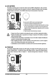
... holder, making them short for more details. GA-EX58-UD5P/UD5 Motherboard - 38 - Turn off . Danger of explosion if the battery is turned off your computer and unplug the power cord before replacing the battery. • Replace the battery with local environmental regulations. 22) PHASE LED The number of purchase or local dealer if...
... holder, making them short for more details. GA-EX58-UD5P/UD5 Motherboard - 38 - Turn off . Danger of explosion if the battery is turned off your computer and unplug the power cord before replacing the battery. • Replace the battery with local environmental regulations. 22) PHASE LED The number of purchase or local dealer if...

Manual
Page 39
The higher the memory loading, the more the number of lighted LEDs. 24) DDR PHASE LED The number of lighted LEDs indicates the memory loading. 23) NB PHASE LED The number of lighted LEDs. - 39 - Hardware Installation The higher the North Bridge loading, the more the number of lighted LEDs indicates the North Bridge loading.
The higher the memory loading, the more the number of lighted LEDs. 24) DDR PHASE LED The number of lighted LEDs indicates the memory loading. 23) NB PHASE LED The number of lighted LEDs. - 39 - Hardware Installation The higher the North Bridge loading, the more the number of lighted LEDs indicates the North Bridge loading.

Manual
Page 85
...GIGABYTE Dynamic Energy Saver Advanced shows how much power they have saved in taskbar) 16 INFO/Help 17 Live Utility Update (Check for the latest utility version) • The above data is for reference only. Button Information Table Button Description 1 Dynamic Energy Saver On/Off Switch (Default: Off) 2 Motherboard Phase LED.... Actual results may vary depending on testing method. - 85 - Featuring an advanced proprietary hardware and software design, GIGABYTE Dynamic Energy Saver Advanced is able to run in a set period of the button. Meter Mode - The Dynamic ...
...GIGABYTE Dynamic Energy Saver Advanced shows how much power they have saved in taskbar) 16 INFO/Help 17 Live Utility Update (Check for the latest utility version) • The above data is for reference only. Button Information Table Button Description 1 Dynamic Energy Saver On/Off Switch (Default: Off) 2 Motherboard Phase LED.... Actual results may vary depending on testing method. - 85 - Featuring an advanced proprietary hardware and software design, GIGABYTE Dynamic Energy Saver Advanced is able to run in a set period of the button. Meter Mode - The Dynamic ...

Manual
Page 86
...the total power saving reaches 99999999 Watts. Button Information Table Button Description 1 Dynamic Energy Saver On/Off Switch (Default: Off) 2 Motherboard Phase LED On/Off Switch (Default: On) 3 Dynamic CPU Frequency Function On/Off Switch (Default: Off) 4 CPU Throttling Display 5 3-Level CPU ... have accumulated in taskbar) 15 INFO/Help 16 Live Utility Update (Check for the first time . (Note 4) Total Mode - GA-EX58-UD5P/UD5 Motherboard - 86 - Re-enter the application only if you want to work with Dynamic Frequency Function; system performance may be affected...
...the total power saving reaches 99999999 Watts. Button Information Table Button Description 1 Dynamic Energy Saver On/Off Switch (Default: Off) 2 Motherboard Phase LED On/Off Switch (Default: On) 3 Dynamic CPU Frequency Function On/Off Switch (Default: Off) 4 CPU Throttling Display 5 3-Level CPU ... have accumulated in taskbar) 15 INFO/Help 16 Live Utility Update (Check for the first time . (Note 4) Total Mode - GA-EX58-UD5P/UD5 Motherboard - 86 - Re-enter the application only if you want to work with Dynamic Frequency Function; system performance may be affected...

Manual
Page 121
...-Virus code 1. Program daylight saving 3. Build MP table 2. Clear screen & display summary table 7. Appendix Program boot up speed 4. Boot BIOS support (popup menu) Update keyboard LED & typematic rate 1. Initialize power-saving (optional) 3. Build MSIRQ routing table Boot attempt (INT 19h) - 121 - Chipset final initialization 5. Load CMOS time into DOS timer tick...
...-Virus code 1. Program daylight saving 3. Build MP table 2. Clear screen & display summary table 7. Appendix Program boot up speed 4. Boot BIOS support (popup menu) Update keyboard LED & typematic rate 1. Initialize power-saving (optional) 3. Build MSIRQ routing table Boot attempt (INT 19h) - 121 - Chipset final initialization 5. Load CMOS time into DOS timer tick...


