Manual
Page 5
Chapter 3 Drivers Installation 73 3-1 Installing Chipset Drivers 73 3-2 Application Software 74 3-3 Technical Manuals 74 3-4 Contact ...75 3-5 System ...75 ...89 4-8 Teaming ...90 Chapter 5 Appendix ...91 5-1 Configuring SATA Hard Drive(s 91 5-1-1 Configuring Intel ICH10R SATA Controllers 91 5-1-2 Configuring GIGABYTE SATA2/JMB322 SATA Controller 97 5-1-3 Making a SATA RAID/AHCI Driver Diskette 99 5-1-4 Installing the SATA RAID/AHCI Driver and Operating System 101...5-3-2 Troubleshooting Procedure 116 5-4 POST Error Code 118 5-5 Regulatory Statements 122 "*" Only for GA-EX58-UD5P. - 5 -
Chapter 3 Drivers Installation 73 3-1 Installing Chipset Drivers 73 3-2 Application Software 74 3-3 Technical Manuals 74 3-4 Contact ...75 3-5 System ...75 ...89 4-8 Teaming ...90 Chapter 5 Appendix ...91 5-1 Configuring SATA Hard Drive(s 91 5-1-1 Configuring Intel ICH10R SATA Controllers 91 5-1-2 Configuring GIGABYTE SATA2/JMB322 SATA Controller 97 5-1-3 Making a SATA RAID/AHCI Driver Diskette 99 5-1-4 Installing the SATA RAID/AHCI Driver and Operating System 101...5-3-2 Troubleshooting Procedure 116 5-4 POST Error Code 118 5-5 Regulatory Statements 122 "*" Only for GA-EX58-UD5P. - 5 -

Manual
Page 10
...the internal IEEE 1394a headers) GA-EX58-UD5P/UD5 Motherboard - 10 - TSB43AB23 chip Up to 3 IEEE 1394a ports (1 on the back panel, 2 via the IEEE 1394a brackets connected to 1 floppy disk drive T.I. 1-2 Product Specifications CPU QPI Chipset Memory Audio LAN Expansion Slots ... SATA2_2, SATA2_3, SATA2_4, SATA2_5) supporting up to 4 SA TA 3Gb/s devices (Note 4) - Support for SATA RAID 0, RAID 1, RAID 5, and RAID 10 GIGABYTE SATA2 chip: - 1 x IDE connector supporting ATA-133/100/66/33 and up to 2 IDE devices 2 x JMB322 chips (Smart Backup): - 4 x SATA ...
...the internal IEEE 1394a headers) GA-EX58-UD5P/UD5 Motherboard - 10 - TSB43AB23 chip Up to 3 IEEE 1394a ports (1 on the back panel, 2 via the IEEE 1394a brackets connected to 1 floppy disk drive T.I. 1-2 Product Specifications CPU QPI Chipset Memory Audio LAN Expansion Slots ... SATA2_2, SATA2_3, SATA2_4, SATA2_5) supporting up to 4 SA TA 3Gb/s devices (Note 4) - Support for SATA RAID 0, RAID 1, RAID 5, and RAID 10 GIGABYTE SATA2 chip: - 1 x IDE connector supporting ATA-133/100/66/33 and up to 2 IDE devices 2 x JMB322 chips (Smart Backup): - 4 x SATA ...

Manual
Page 16
... two DDR3 memory modules are installed, a message which says memory is installed, be used. GA-EX58-UD5P/UD5 Motherboard - 16 - It is recommended that the motherboard supports the memory. The six DDR3 memory...When enabling Dual Channel mode with three memory modules, be sure to be sure to chipset limitation, read the following guidelines before installing the memory in the DDR3_1, DDR3_3 and ... DDR3_4 DDR3_3 DDR3_6 DDR3_5 Two Modules - - A memory module can be used . (Go to GIGABYTE's website for the latest memory support list.) • Always turn off the computer and unplug the...
... two DDR3 memory modules are installed, a message which says memory is installed, be used. GA-EX58-UD5P/UD5 Motherboard - 16 - It is recommended that the motherboard supports the memory. The six DDR3 memory...When enabling Dual Channel mode with three memory modules, be sure to be sure to chipset limitation, read the following guidelines before installing the memory in the DDR3_1, DDR3_3 and ... DDR3_4 DDR3_3 DDR3_6 DDR3_5 Two Modules - - A memory module can be used . (Go to GIGABYTE's website for the latest memory support list.) • Always turn off the computer and unplug the...
Manual
Page 45
... not to alter the default settings to prevent system instability or other unexpected results. (Inadequately altering the settings may result in system's failure to CPU, chipset, or memory and reduce the useful life of these components.
... not to alter the default settings to prevent system instability or other unexpected results. (Inadequately altering the settings may result in system's failure to CPU, chipset, or memory and reduce the useful life of these components.
Manual
Page 47
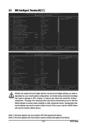
Depending on CPU loading, Intel® EIST technology can function as multiple virtual systems. (Default: Enabled) Bi-Directional PROCHOT (Note) Enabled When the CPU or chipset detects that supports this feature. UnCore Frequency Allows you install a CPU that an overheating is occurring, PROCHOT signals will be reduced when the CPU is ...
Depending on CPU loading, Intel® EIST technology can function as multiple virtual systems. (Default: Enabled) Bi-Directional PROCHOT (Note) Enabled When the CPU or chipset detects that supports this feature. UnCore Frequency Allows you install a CPU that an overheating is occurring, PROCHOT signals will be reduced when the CPU is ...

Manual
Page 73
... drivers. • After the drivers are recommended to install. Failure to My Computer, double-click the optical drive and execute the Run.exe program.) 3-1 Installing Chipset Drivers After inserting the driver disk, "Xpress Install" will restart your system and then list all the recommended drivers. After the system restart, "Xpress Install...
... drivers. • After the drivers are recommended to install. Failure to My Computer, double-click the optical drive and execute the Run.exe program.) 3-1 Installing Chipset Drivers After inserting the driver disk, "Xpress Install" will restart your system and then list all the recommended drivers. After the system restart, "Xpress Install...

Manual
Page 84
... speed alarm. GA-EX58-UD5P/UD5 Motherboard - 84 - Before you to specify a C.I.A.2 level and a Smart Fan mode. The HW Monitor tab allows you do overclock/overvoltage in Windows environment. Grayed-out area(s) indicates that you to monitor hardware temperature, volt - 4-3 EasyTune 6 GIGABYTE's EasyTune 6 is... and motherboard. After making changes, be changed linearly based on a specific slot to the hardware components such as CPU, chipset, and memory and reduce the useful life of EasyTune 6, or system instability or other unexpected results may differ by motherboard model...
... speed alarm. GA-EX58-UD5P/UD5 Motherboard - 84 - Before you to specify a C.I.A.2 level and a Smart Fan mode. The HW Monitor tab allows you do overclock/overvoltage in Windows environment. Grayed-out area(s) indicates that you to monitor hardware temperature, volt - 4-3 EasyTune 6 GIGABYTE's EasyTune 6 is... and motherboard. After making changes, be changed linearly based on a specific slot to the hardware components such as CPU, chipset, and memory and reduce the useful life of EasyTune 6, or system instability or other unexpected results may differ by motherboard model...

Manual
Page 105
..., click the volume and its status in the Start Menu. Performing the Rebuild in the Operating System While in the operating system, make sure the chipset driver has been installed from Programs in the information pane will display as Normal. - 105 - Follow the on-screen instruc-
..., click the volume and its status in the Start Menu. Performing the Rebuild in the Operating System While in the operating system, make sure the chipset driver has been installed from Programs in the information pane will display as Normal. - 105 - Follow the on-screen instruc-

Manual
Page 118
... Auto detect ports for Winbond 977 series Super I /O chips Test F000h segment shadow to SPURIOUS_soft_HDLR Initial EARLY_PM_INIT switch 1. Program basic chipset registers Detect memory - Test special keyboard controller for keyboard & mouse followed by OEM customers Initial onboard clock generator if Early_Init_Onboard_Generator is ...Auto detect flash type to load appropriate flash R/W codes into BIOS stack. If CMOS checksum fails, use default value instead GA-EX58-UD5P/UD5 Motherboard - 118 - Load CMOS settings into the run time area in F000 for ESCD & DMI support Use walking 1's ...
... Auto detect ports for Winbond 977 series Super I /O chips Test F000h segment shadow to SPURIOUS_soft_HDLR Initial EARLY_PM_INIT switch 1. Program basic chipset registers Detect memory - Test special keyboard controller for keyboard & mouse followed by OEM customers Initial onboard clock generator if Early_Init_Onboard_Generator is ...Auto detect flash type to load appropriate flash R/W codes into BIOS stack. If CMOS checksum fails, use default value instead GA-EX58-UD5P/UD5 Motherboard - 118 - Load CMOS settings into the run time area in F000 for ESCD & DMI support Use walking 1's ...

Manual
Page 119
... for P6 class CPU & program CPU with proper cacheable range 3. Initialize double-byte language font (optional) 2. Initialize L2 cache for P6 class CPU 4. Program early chipset according to CMOS setup Example: onboard IDE controller 4. See also POST 63h Test DMA Channel 0 Test DMA Channel 1 Test DMA page registers Test 8254 Test...
... for P6 class CPU & program CPU with proper cacheable range 3. Initialize double-byte language font (optional) 2. Initialize L2 cache for P6 class CPU 4. Program early chipset according to CMOS setup Example: onboard IDE controller 4. See also POST 63h Test DMA Channel 0 Test DMA Channel 1 Test DMA page registers Test 8254 Test...

Manual
Page 120
... is not defined Initialize PS/2 Mouse Prepare memory size information for function call: INT 15h ax=E820h Turn on L2 cache Program chipset registers according to items described in Setup is set to onboard COM ports if the corresponding item in Setup & Auto-configuration table ... chipset power management hook 2. Set up floppy related fields in stack back to all IDE devices: HDD, LS120, ZIP, CDROM... Early ISA PnP initialization - If password is set , ask for password Save all data in 40:hardware Detect & install all ISA PnP devices 2. APM initialization GA-EX58-UD5P/UD5 ...
... is not defined Initialize PS/2 Mouse Prepare memory size information for function call: INT 15h ax=E820h Turn on L2 cache Program chipset registers according to items described in Setup is set to onboard COM ports if the corresponding item in Setup & Auto-configuration table ... chipset power management hook 2. Set up floppy related fields in stack back to all IDE devices: HDD, LS120, ZIP, CDROM... Early ISA PnP initialization - If password is set , ask for password Save all data in 40:hardware Detect & install all ISA PnP devices 2. APM initialization GA-EX58-UD5P/UD5 ...

Manual
Page 121
... to 20h or 19h 4. Program daylight saving 3. Build MP table 2. Initialize power-saving (optional) 3. Program boot up speed 4. Load CMOS time into DOS timer tick 5. Chipset final initialization 5. Enable L2 cache 2. Clear screen & display summary table 7. POST (hex) 8Fh 93h 94h 95h 96h FFh Description Clear noise of IRQs Read HDD...
... to 20h or 19h 4. Program daylight saving 3. Build MP table 2. Initialize power-saving (optional) 3. Program boot up speed 4. Load CMOS time into DOS timer tick 5. Chipset final initialization 5. Enable L2 cache 2. Clear screen & display summary table 7. POST (hex) 8Fh 93h 94h 95h 96h FFh Description Clear noise of IRQs Read HDD...


