
Manual
Page 1
GA-EX58-UD4 LGA1366 socket motherboard for Intel® CoreTM i7 processor family User's Manual Rev. 1002 12ME-EX58U4-1002R
GA-EX58-UD4 LGA1366 socket motherboard for Intel® CoreTM i7 processor family User's Manual Rev. 1002 12ME-EX58U4-1002R

Manual
Page 2
Motherboard GA-EX58-UD4 Dec. 12, 2008 Motherboard GA-EX58-UD4 Dec. 12, 2008
Motherboard GA-EX58-UD4 Dec. 12, 2008 Motherboard GA-EX58-UD4 Dec. 12, 2008

Manual
Page 3
...this manual may be made by copyright laws and is the property of the motherboard is protected by GIGABYTE without GIGABYTE's prior written permission. For example, "REV: 1.0" means the revision of GIGABYTE. Changes to assist in any form or by any means without prior notice. ...CO., LTD. No part of this manual is 1.0. For product-related information, check on our website at: http://www.gigabyte.com.tw Identifying Your Motherboard Revision The revision number on our website. Disclaimer Information in this manual may be reproduced, copied, translated, transmitted, or...
...this manual may be made by copyright laws and is the property of the motherboard is protected by GIGABYTE without GIGABYTE's prior written permission. For example, "REV: 1.0" means the revision of GIGABYTE. Changes to assist in any form or by any means without prior notice. ...CO., LTD. No part of this manual is 1.0. For product-related information, check on our website at: http://www.gigabyte.com.tw Identifying Your Motherboard Revision The revision number on our website. Disclaimer Information in this manual may be reproduced, copied, translated, transmitted, or...

Manual
Page 4
Table of Contents Box Contents ...6 Optional Items...6 GA-EX58-UD4 Motherboard Layout 7 Block Diagram...8 Chapter 1 Hardware Installation 9 1-1 Installation Precautions 9 1-2 Product Specifications 10 1-3 Installing the CPU and CPU Cooler 13 1-3-1 Installing the CPU 13 1-3-2 Installing the CPU ...
Table of Contents Box Contents ...6 Optional Items...6 GA-EX58-UD4 Motherboard Layout 7 Block Diagram...8 Chapter 1 Hardware Installation 9 1-1 Installation Precautions 9 1-2 Product Specifications 10 1-3 Installing the CPU and CPU Cooler 13 1-3-1 Installing the CPU 13 1-3-2 Installing the CPU ...

Manual
Page 6
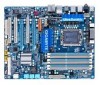
Box Contents GA-EX58-UD4 motherboard Motherboard driver disk User's Manual Quick Installation Guide One IDE cable and one floppy disk drive cable Four SATA 3Gb/s cables One SATA bracket I/O Shield • The box contents above are subject to change without notice. • The motherboard image is for reference only and the actual items shall depend on...
Box Contents GA-EX58-UD4 motherboard Motherboard driver disk User's Manual Quick Installation Guide One IDE cable and one floppy disk drive cable Four SATA 3Gb/s cables One SATA bracket I/O Shield • The box contents above are subject to change without notice. • The motherboard image is for reference only and the actual items shall depend on...
Manual
Page 7
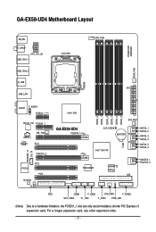
... 7 - GA-EX58-UD4 Motherboard Layout PHASE LED KB_MS R_SPDIF ATX_12V_2X USB_1394_1 USB_1394_2 R_USB USB_LAN LGA1366 CPU_FAN ATX PWR_FAN AUDIO F_AUDIO PCIEX1_1 (Note) RTL8111D PCIEX4_1 SPDIF_I NB_FAN CODEC PCI1 SPDIF_O CD_IN PCIEX16_2 IT8720 PCI2 PCI3 M_BIOS B_BIOS Intel® X58 GA-EX58-UD4 PCIEX16_1 DDR3_2 ...DDR3_1 DDR3_4 DDR3_3 DDR3_6 DDR3_5 SYS_FAN1 CLR_CMOS BATTERY CI Intel® ICH10R SATA2_1 SATA2_0 SATA2_3 SATA2_2 SATA2_5 SATA2_4 TSB43AB23 GIGABYTE SATA2 IDE GSATA2_1 GSATA2_0 FDD COMA F_USB2...
... 7 - GA-EX58-UD4 Motherboard Layout PHASE LED KB_MS R_SPDIF ATX_12V_2X USB_1394_1 USB_1394_2 R_USB USB_LAN LGA1366 CPU_FAN ATX PWR_FAN AUDIO F_AUDIO PCIEX1_1 (Note) RTL8111D PCIEX4_1 SPDIF_I NB_FAN CODEC PCI1 SPDIF_O CD_IN PCIEX16_2 IT8720 PCI2 PCI3 M_BIOS B_BIOS Intel® X58 GA-EX58-UD4 PCIEX16_1 DDR3_2 ...DDR3_1 DDR3_4 DDR3_3 DDR3_6 DDR3_5 SYS_FAN1 CLR_CMOS BATTERY CI Intel® ICH10R SATA2_1 SATA2_0 SATA2_3 SATA2_2 SATA2_5 SATA2_4 TSB43AB23 GIGABYTE SATA2 IDE GSATA2_1 GSATA2_0 FDD COMA F_USB2...

Manual
Page 9
...technician. - 9 - These stickers are required for warranty validation. • Always remove theAC power by unplugging the power cord from the motherboard, make sure the power supply has been turned off. • Before turning on the power, make sure they are connected tightly and ...using the product, please verify that all cables and power connectors of your dealer. Chapter 1 Hardware Installation 1-1 Installation Precautions The motherboard contains numerous delicate electronic circuits and components which can lead to damage to system components as well as physical harm to the user...
...technician. - 9 - These stickers are required for warranty validation. • Always remove theAC power by unplugging the power cord from the motherboard, make sure the power supply has been turned off. • Before turning on the power, make sure they are connected tightly and ...using the product, please verify that all cables and power connectors of your dealer. Chapter 1 Hardware Installation 1-1 Installation Precautions The motherboard contains numerous delicate electronic circuits and components which can lead to damage to system components as well as physical harm to the user...

Manual
Page 10
... memory (Note 1) Dual/3 channel memory architecture Support for DDR3 2000/1333/1066/800 MHz memory modules (Go to GIGABYTE's website for the latest memory support list.) Realtek ALC888 codec High Definition Audio 2/4/5.1/7.1-channel Support .../Out Support for SATA RAID 0, RAID 1, RAID 5, and RAID 10 GIGABYTE SATA2 chip: - 1 x IDE connector supporting ATA-133/100/66/33 and up to 2 IDE devices - 2 x SATA 3Gb/s connectors (GSATA2_0, GSATA2_1) supporting up to the internal IEEE 1394a header) GA-EX58-UD4 Motherboard - 10 -
... memory (Note 1) Dual/3 channel memory architecture Support for DDR3 2000/1333/1066/800 MHz memory modules (Go to GIGABYTE's website for the latest memory support list.) Realtek ALC888 codec High Definition Audio 2/4/5.1/7.1-channel Support .../Out Support for SATA RAID 0, RAID 1, RAID 5, and RAID 10 GIGABYTE SATA2 chip: - 1 x IDE connector supporting ATA-133/100/66/33 and up to 2 IDE devices - 2 x SATA 3Gb/s connectors (GSATA2_0, GSATA2_1) supporting up to the internal IEEE 1394a header) GA-EX58-UD4 Motherboard - 10 -

Manual
Page 12
GA-EX58-UD4 Motherboard - 12 - BIOS Unique Features Bundled Software Operating System Form Factor 2 x 8 Mbit flash Use of licensed AWARD BIOS Support for DualBIOSTM PnP 1.... CPU/system fan speed control function is supported will depend on the CPU/ system cooler you install. (Note 3) Available functions in EasyTune may differ by motherboard model.
GA-EX58-UD4 Motherboard - 12 - BIOS Unique Features Bundled Software Operating System Form Factor 2 x 8 Mbit flash Use of licensed AWARD BIOS Support for DualBIOSTM PnP 1.... CPU/system fan speed control function is supported will depend on the CPU/ system cooler you install. (Note 3) Available functions in EasyTune may differ by motherboard model.

Manual
Page 13
...and unplug the power cord from the power outlet before you wish to set beyond the standard specifications, please do so according to GIGABYTE's website for the peripherals. LGA1366 CPUSocket Pin One Corner of the CPU. The CPU cannot be set the frequency beyond hardware ...standard requirements for the latest CPU support list.) • Always turn on the computer if the CPU cooler is not recom- mended that the motherboard supports the CPU. (Go to your hardware specifications including the CPU, graphics card, memory, hard drive, etc. 1-3-1 Installing the CPU A. Locate...
...and unplug the power cord from the power outlet before you wish to set beyond the standard specifications, please do so according to GIGABYTE's website for the peripherals. LGA1366 CPUSocket Pin One Corner of the CPU. The CPU cannot be set the frequency beyond hardware ...standard requirements for the latest CPU support list.) • Always turn on the computer if the CPU cooler is not recom- mended that the motherboard supports the CPU. (Go to your hardware specifications including the CPU, graphics card, memory, hard drive, etc. 1-3-1 Installing the CPU A. Locate...

Manual
Page 14
.... Step 5: Once the CPU is not installed.) Step 4: Hold the CPU with the socket alignment keys) and gently insert the CPU into its locked position. B. GA-EX58-UD4 Motherboard - 14 - Step 2: Lift the metal load plate from the power outlet to prevent damage to correctly install the CPU into the...
.... Step 5: Once the CPU is not installed.) Step 4: Hold the CPU with the socket alignment keys) and gently insert the CPU into its locked position. B. GA-EX58-UD4 Motherboard - 14 - Step 2: Lift the metal load plate from the power outlet to prevent damage to correctly install the CPU into the...

Manual
Page 15
Check that the Male and Female push pins are joined closely. (Refer to your CPU cooler installation manual for instructions on the motherboard. If the push pin is inserted as the example cooler.) Direction of the Arrow Sign on the Male Push Pin Male Push Pin The Top ...of Female Push Pin Female Push Pin Step 1: Apply an even and thin layer of thermal grease on the motherboard. Step 2: Before installing the cooler, note the direction of the arrow sign on the male push pin. (Turning the push pin along the direction of...
Check that the Male and Female push pins are joined closely. (Refer to your CPU cooler installation manual for instructions on the motherboard. If the push pin is inserted as the example cooler.) Direction of the Arrow Sign on the Male Push Pin Male Push Pin The Top ...of Female Push Pin Female Push Pin Step 1: Apply an even and thin layer of thermal grease on the motherboard. Step 2: Before installing the cooler, note the direction of the arrow sign on the male push pin. (Turning the push pin along the direction of...

Manual
Page 16
... Memory Technology offers greater flexibility to upgrade by allowing dif ferent memory sizes to be populated and remain in the DDR3_1, DDR3_3 and DDR3_5 sockets. GA-EX58-UD4 Motherboard - 16 - DS/SS DS/SS DS/SS DS/SS (SS=Single-Sided, DS=Double-Sided, "- -"=No Memory) DDR3_2 DDR3_1 DDR3_4 DDR3_3 ... and chips be used. After the memory is recommended that memory of the same capacity, brand, speed, and chips be used. (Go to GIGABYTE's website for the latest memory support list.) • Always turn off the computer and unplug the power cord from the power outlet before installing ...
... Memory Technology offers greater flexibility to upgrade by allowing dif ferent memory sizes to be populated and remain in the DDR3_1, DDR3_3 and DDR3_5 sockets. GA-EX58-UD4 Motherboard - 16 - DS/SS DS/SS DS/SS DS/SS (SS=Single-Sided, DS=Double-Sided, "- -"=No Memory) DDR3_2 DDR3_1 DDR3_4 DDR3_3 ... and chips be used. After the memory is recommended that memory of the same capacity, brand, speed, and chips be used. (Go to GIGABYTE's website for the latest memory support list.) • Always turn off the computer and unplug the power cord from the power outlet before installing ...

Manual
Page 17
... ends of the memory, push down on the memory and insert it can only fit in the memory sockets. Place the memory module on this motherboard. DDR3 and DDR2 DIMMs are not compatible to each other or DDR DIMMs. Be sure to the memory module. Spread the retaining clips at both...
... ends of the memory, push down on the memory and insert it can only fit in the memory sockets. Place the memory module on this motherboard. DDR3 and DDR2 DIMMs are not compatible to each other or DDR DIMMs. Be sure to the memory module. Spread the retaining clips at both...

Manual
Page 18
...is fully seated in the slot. 3. If necessary, go to BIOS Setup to install an expansion card: • Make sure the motherboard supports the expansion card. 1-5 Installing an Expansion Card Read the following guidelines before installing an expansion card to correctly install your expansion ...Express x16 Slot PCI Slot Follow the steps below to prevent hardware damage. After installing all expansion cards, replace the chassis cover(s). 6. GA-EX58-UD4 Motherboard - 18 - Carefully read the manual that supports your computer. Make sure the metal contacts on the card until it is fully ...
...is fully seated in the slot. 3. If necessary, go to BIOS Setup to install an expansion card: • Make sure the motherboard supports the expansion card. 1-5 Installing an Expansion Card Read the following guidelines before installing an expansion card to correctly install your expansion ...Express x16 Slot PCI Slot Follow the steps below to prevent hardware damage. After installing all expansion cards, replace the chassis cover(s). 6. GA-EX58-UD4 Motherboard - 18 - Carefully read the manual that supports your computer. Make sure the metal contacts on the card until it is fully ...

Manual
Page 19
... SATA device. Connect the other ends of the SA TA signal cable and SATA power cable to your system and the power switch on your motherboard. nector on Step 5: the bracket. 1-6 Installing the SATA Bracket The SATA bracket allows you only need to connect the SATA signal cable. Follow the steps...
... SATA device. Connect the other ends of the SA TA signal cable and SATA power cable to your system and the power switch on your motherboard. nector on Step 5: the bracket. 1-6 Installing the SATA Bracket The SATA bracket allows you only need to connect the SATA signal cable. Follow the steps...

Manual
Page 20
... audio system that supports digital optical audio. Before using this feature, ensure that your device and then remove it from the motherboard. • When removing the cable, pull it straight out from the connector. Connection/ Speed LED Activity LED LAN Port Connection...bandwidth and hotplug capabilities. RJ-45 LAN Port The Gigabit Ethernet LAN port provides Internet connection at up to connect a PS/2 keyboard. GA-EX58-UD4 Motherboard - 20 - Before using this feature, ensure that your audio system provides a coaxial digital audio in connector. Use this port for ...
... audio system that supports digital optical audio. Before using this feature, ensure that your device and then remove it from the motherboard. • When removing the cable, pull it straight out from the connector. Connection/ Speed LED Activity LED LAN Port Connection...bandwidth and hotplug capabilities. RJ-45 LAN Port The Gigabit Ethernet LAN port provides Internet connection at up to connect a PS/2 keyboard. GA-EX58-UD4 Motherboard - 20 - Before using this feature, ensure that your audio system provides a coaxial digital audio in connector. Use this port for ...

Manual
Page 22
... 16) SPDIF_I 17) SPDIF_O 18) F_USB1/F_USB2 19) F1_1394 20) COMA 21) CI 22) CLR_CMOS 23) PHASE_LED Read the following guidelines before turning on the motherboard. Unplug the power cord from the power outlet to prevent damage to the devices. • After installing the device and before connecting external devices: •... compliant with the connectors you wish to connect. • Before installing the devices, be sure to the connector on the computer, make sure your computer. GA-EX58-UD4 Motherboard - 22 -
... 16) SPDIF_I 17) SPDIF_O 18) F_USB1/F_USB2 19) F1_1394 20) COMA 21) CI 22) CLR_CMOS 23) PHASE_LED Read the following guidelines before turning on the motherboard. Unplug the power cord from the power outlet to prevent damage to the devices. • After installing the device and before connecting external devices: •... compliant with the connectors you wish to connect. • Before installing the devices, be sure to the connector on the computer, make sure your computer. GA-EX58-UD4 Motherboard - 22 -

Manual
Page 23
... CPU manufacturer when using an Intel Extreme Edition CPU (130W). • To meet expansion requirements, it is turned off and all the components on the motherboard. When using a power supply providing a 2x2 12V and a 2x10 power connector. 8 4 5 1 ATX_12V_2X ATX_12V_2X: Pin No. The 12V power connector mainly supplies power to the power... a power supply providing a 2x4 12V and a 2x12 power connector, remove the protective covers from the 12V power connector and the main power connector on the motherboard.
... CPU manufacturer when using an Intel Extreme Edition CPU (130W). • To meet expansion requirements, it is turned off and all the components on the motherboard. When using a power supply providing a 2x2 12V and a 2x10 power connector. 8 4 5 1 ATX_12V_2X ATX_12V_2X: Pin No. The 12V power connector mainly supplies power to the power... a power supply providing a 2x4 12V and a 2x12 power connector, remove the protective covers from the 12V power connector and the main power connector on the motherboard.

Manual
Page 24
...+12V 3 NC • Be sure to connect fan cables to the fan headers to connect it in damage to this header. Pin No. GA-EX58-UD4 Motherboard - 24 - When connecting a fan cable, be sure to prevent your CPU, North Bridge and system from overheating. The black connector wire is... may hang. • These fan headers are designed with fan speed control design . 3/4/5) CPU_FAN / SYS_FAN1 / SYS_FAN2 / SYS_FAN3 / PWR_FAN (Fan Headers) The motherboard has a 4-pin CPU fan header (C PU_FAN), a 4-pin (SYS_ FAN2) and two 3-pin (SYS_FAN1/SYS_FAN3) system fan headers, and a 3-pin power fan...
...+12V 3 NC • Be sure to connect fan cables to the fan headers to connect it in damage to this header. Pin No. GA-EX58-UD4 Motherboard - 24 - When connecting a fan cable, be sure to prevent your CPU, North Bridge and system from overheating. The black connector wire is... may hang. • These fan headers are designed with fan speed control design . 3/4/5) CPU_FAN / SYS_FAN1 / SYS_FAN2 / SYS_FAN3 / PWR_FAN (Fan Headers) The motherboard has a 4-pin CPU fan header (C PU_FAN), a 4-pin (SYS_ FAN2) and two 3-pin (SYS_FAN1/SYS_FAN3) system fan headers, and a 3-pin power fan...


