Manual
Page 4
Table of Contents Box Contents ...6 OptionalItems ...6 GA-EX58-EXTREME Motherboard Layout 7 Block Diagram ...8 Chapter 1 Hardware Installation 9 1-1 Installation Precautions 9 1-2 Product Specifications 10 1-3 Installing the CPU and CPU Cooler 13 1-3-1 Installing the CPU 13 1-3-2 Installing the CPU ...
Table of Contents Box Contents ...6 OptionalItems ...6 GA-EX58-EXTREME Motherboard Layout 7 Block Diagram ...8 Chapter 1 Hardware Installation 9 1-1 Installation Precautions 9 1-2 Product Specifications 10 1-3 Installing the CPU and CPU Cooler 13 1-3-1 Installing the CPU 13 1-3-2 Installing the CPU ...
Manual
Page 6
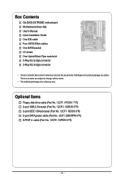
... 1394a bracket (Part No. 12CF1-1IE008-0*R) 2-port SATA power cable (Part No. 12CF1-2SERPW-0*R) S/PDIF in cable (Part No. 12CR1-1SPDIN-0*R) - 6 - Box Contents GA-EX58-EXTREME motherboard Motherboard driver disk User's Manual Quick Installation Guide One IDE cable Four SATA 3Gb/s cables One SATA bracket I/O shield One Hybrid Silent-Pipe module kit 2-Way... SLI bridge connector 3-Way SLI bridge connector • The box contents above are subject to change without notice. • The motherboard image is for reference only and the actual items shall depend on product package you obtain.
... 1394a bracket (Part No. 12CF1-1IE008-0*R) 2-port SATA power cable (Part No. 12CF1-2SERPW-0*R) S/PDIF in cable (Part No. 12CR1-1SPDIN-0*R) - 6 - Box Contents GA-EX58-EXTREME motherboard Motherboard driver disk User's Manual Quick Installation Guide One IDE cable Four SATA 3Gb/s cables One SATA bracket I/O shield One Hybrid Silent-Pipe module kit 2-Way... SLI bridge connector 3-Way SLI bridge connector • The box contents above are subject to change without notice. • The motherboard image is for reference only and the actual items shall depend on product package you obtain.
Manual
Page 7
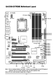
GA-EX58-EXTREME Motherboard Layout KB_MS SYS_FAN3 R_SPDIF V1394-1 ATX_12V_2X CMOS_SW R_USB CPU Voltage L1/2/3 LGA1366 CPU_FAN CPU TEMP L1/2 PW_SW FREQ. For a longer expansion card, use other expansion ... DDR3_2 DDR3_1 DDR3_4 DDR3_3 DDR3_6 DDR3_5 SYS_FAN1 SB Voltage L1/2/3 BATTERY CLR_CMOS Intel® ICH10R JMB322 JMB322 SPDIF_O CD_IN PCI2 IT8720 M_BIOS B_BIOS TSB43AB23 PCIEX8_1 GIGABYTE SATA2 PWR_LED CI Debug LED(Note 2) IDE NB PHASE LED SATA2_1 SATA2_0 SATA2_3 SATA2_2 SATA2_5 SATA2_4 GSATA2_1 GSATA2_0 GSATA2_3 GSATA2_2 FDD F1_1394 F_USB2 F_PANEL SYS_FAN2...
GA-EX58-EXTREME Motherboard Layout KB_MS SYS_FAN3 R_SPDIF V1394-1 ATX_12V_2X CMOS_SW R_USB CPU Voltage L1/2/3 LGA1366 CPU_FAN CPU TEMP L1/2 PW_SW FREQ. For a longer expansion card, use other expansion ... DDR3_2 DDR3_1 DDR3_4 DDR3_3 DDR3_6 DDR3_5 SYS_FAN1 SB Voltage L1/2/3 BATTERY CLR_CMOS Intel® ICH10R JMB322 JMB322 SPDIF_O CD_IN PCI2 IT8720 M_BIOS B_BIOS TSB43AB23 PCIEX8_1 GIGABYTE SATA2 PWR_LED CI Debug LED(Note 2) IDE NB PHASE LED SATA2_1 SATA2_0 SATA2_3 SATA2_2 SATA2_5 SATA2_4 GSATA2_1 GSATA2_0 GSATA2_3 GSATA2_2 FDD F1_1394 F_USB2 F_PANEL SYS_FAN2...
Manual
Page 10
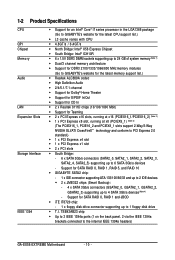
...Note 1) Dual/3 channel memory architecture Support for DDR3 2100/1333/1066/800 MHz memory modules (Go to GIGABYTE's website for the latest memory support list.) Realtek ALC889A codec High Definition Audio 2/4/5.1/7.1-channel &#...RAID 5, and RAID 10 GIGABYTE SATA2 chip: - 1 x IDE connector supporting ATA-133/100/66/33 and up to 2 IDE devices 2 x JMB322 chips (Smart Backup): - 4 x SATA 3Gb/s connectors (GSATA2_0, GSATA2_1, GSATA2_2, GSATA2_3) supporting up to the internal IEEE 1394a headers) GA-EX58-EXTREME Motherboard - 10 -
...Note 1) Dual/3 channel memory architecture Support for DDR3 2100/1333/1066/800 MHz memory modules (Go to GIGABYTE's website for the latest memory support list.) Realtek ALC889A codec High Definition Audio 2/4/5.1/7.1-channel &#...RAID 5, and RAID 10 GIGABYTE SATA2 chip: - 1 x IDE connector supporting ATA-133/100/66/33 and up to 2 IDE devices 2 x JMB322 chips (Smart Backup): - 4 x SATA 3Gb/s connectors (GSATA2_0, GSATA2_1, GSATA2_2, GSATA2_3) supporting up to the internal IEEE 1394a headers) GA-EX58-EXTREME Motherboard - 10 -
Manual
Page 12
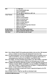
... card, the PCIEX16_2 slot will depend on the CPU/ system cooler you are installing two PCI Express graphics cards, it in EasyTune may differ by motherboard model. GA-EX58-EXTREME Motherboard - 12 - BIOS Unique Features Bundled Software Operating System Form Factor 2 x 8 Mbit flash Use of licensed AWARD BIOS Support for DualBIOSTM ...
... card, the PCIEX16_2 slot will depend on the CPU/ system cooler you are installing two PCI Express graphics cards, it in EasyTune may differ by motherboard model. GA-EX58-EXTREME Motherboard - 12 - BIOS Unique Features Bundled Software Operating System Form Factor 2 x 8 Mbit flash Use of licensed AWARD BIOS Support for DualBIOSTM ...
Manual
Page 14
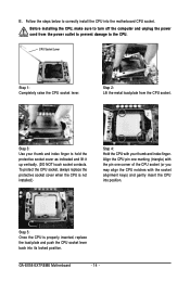
...the power cord from the CPU socket. CPU Socket Lever Step 1: Completely raise the CPU socket lever. Step 3: Use your thumb and index finger. GA-EX58-EXTREME Motherboard - 14 - Before installing the CPU, make sure to correctly install the CPU into position. Step 5: Once the CPU is not installed.) Step ...4: Hold the CPU with the socket alignment keys) and gently insert the CPU into the motherboard CPU socket. To protect the CPU socket, always replace the protective socket cover when the CPU is properly inserted, replace the load plate ...
...the power cord from the CPU socket. CPU Socket Lever Step 1: Completely raise the CPU socket lever. Step 3: Use your thumb and index finger. GA-EX58-EXTREME Motherboard - 14 - Before installing the CPU, make sure to correctly install the CPU into position. Step 5: Once the CPU is not installed.) Step ...4: Hold the CPU with the socket alignment keys) and gently insert the CPU into the motherboard CPU socket. To protect the CPU socket, always replace the protective socket cover when the CPU is properly inserted, replace the load plate ...
Manual
Page 16
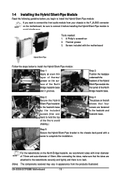
Tools needed: 1. Step 5: Secure the Hybrid Silent-Pipe bracket to the chassis back panel with the motherboard Hybrid Silent-Pipe Follow the steps below to install the Hybrid Silent-Pipe module: Step 1: Apply an even thin layer of thermal grease on the ... module from the products illustrated. 1-4 Installing the Hybrid Silent-Pipe Module Read the following guideline before installing the Hybrid Silent-Pipe module to avoid interference. GA-EX58-EXTREME Motherboard - 16 - A Philip's screwdriver 2. Thermal grease 3. For the waterblocks on the...
Tools needed: 1. Step 5: Secure the Hybrid Silent-Pipe bracket to the chassis back panel with the motherboard Hybrid Silent-Pipe Follow the steps below to install the Hybrid Silent-Pipe module: Step 1: Apply an even thin layer of thermal grease on the ... module from the products illustrated. 1-4 Installing the Hybrid Silent-Pipe Module Read the following guideline before installing the Hybrid Silent-Pipe module to avoid interference. GA-EX58-EXTREME Motherboard - 16 - A Philip's screwdriver 2. Thermal grease 3. For the waterblocks on the...
Manual
Page 18
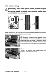
... DDR DIMMs. Be sure to the memory module. Spread the retaining clips at both ends of the memory module. Place the memory module on this motherboard. GA-EX58-EXTREME Motherboard - 18 - 1-5-2 Installing a Memory Before installing a memory module , make sure to turn off the computer and unplug the power cord from the power outlet to prevent...
... DDR DIMMs. Be sure to the memory module. Spread the retaining clips at both ends of the memory module. Place the memory module on this motherboard. GA-EX58-EXTREME Motherboard - 18 - 1-5-2 Installing a Memory Before installing a memory module , make sure to turn off the computer and unplug the power cord from the power outlet to prevent...
Manual
Page 20
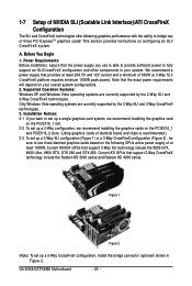
... SLI and 3-Way CrossFireX technologies. 3. Figure 1 Figure 2 (Note) To set up a 3-Way CrossFireX configuration, install the bridge connector (optional) shown in your overall system configurations. 2. GA-EX58-EXTREME Motherboard - 20 - 1-7 Setup of 600W (a 3-Way SLI/ CrossFireX platform requires minimum 1000W peak power). Power Requirements: Before installation, assure that the power supply you want to...
... SLI and 3-Way CrossFireX technologies. 3. Figure 1 Figure 2 (Note) To set up a 3-Way CrossFireX configuration, install the bridge connector (optional) shown in your overall system configurations. 2. GA-EX58-EXTREME Motherboard - 20 - 1-7 Setup of 600W (a 3-Way SLI/ CrossFireX platform requires minimum 1000W peak power). Power Requirements: Before installation, assure that the power supply you want to...
Manual
Page 22
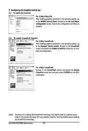
... select 3 GPUS for the GPU combination. (Note) Procedure for more information about enabling SLI/CrossFireX technology. For 3-Way CrossFireX: Browse to the Catalyst Control Center. GA-EX58-EXTREME Motherboard - 22 - Configuring the Graphics Card Driver: C-1 To enable SLI function For 2-Way/3-Way SLI: After installing graphics card driver in the operating system, go to...
... select 3 GPUS for the GPU combination. (Note) Procedure for more information about enabling SLI/CrossFireX technology. For 3-Way CrossFireX: Browse to the Catalyst Control Center. GA-EX58-EXTREME Motherboard - 22 - Configuring the Graphics Card Driver: C-1 To enable SLI function For 2-Way/3-Way SLI: After installing graphics card driver in the operating system, go to...
Manual
Page 24
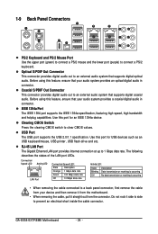
Use this feature, ensure that your device and then remove it from the motherboard. • When removing the cable, pull it side to side to connect a PS/2 keyboard. GA-EX58-EXTREME Motherboard - 24 - IEEE 1394a Port The IEEE 1394 port supports the IEEE 1394a specification, featuring high speed, high bandwidth and hotplug capabilities. USB Port The...
Use this feature, ensure that your device and then remove it from the motherboard. • When removing the cable, pull it side to side to connect a PS/2 keyboard. GA-EX58-EXTREME Motherboard - 24 - IEEE 1394a Port The IEEE 1394 port supports the IEEE 1394a specification, featuring high speed, high bandwidth and hotplug capabilities. USB Port The...
Manual
Page 26
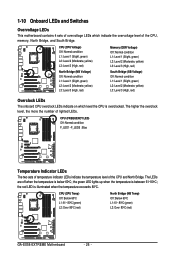
...(green) L2: Over 80oC (red) North Bridge (NB Temp) Off: Below 60oC L1: 61~ 80oC (green) L2: Over 80oC (red) GA-EX58-EXTREME Motherboard - 26 - the green LED lights up when the temperature is below 60oC; the red LED is overclocked. 1-10 Onboard LEDs and Switches Overvoltage LEDs ...This motherboard contains 4 sets of overvoltage LEDs which level the CPU is illuminated when the temperature exceeds 80oC. CPU (CPU Voltage) Off: Normal condition...
...(green) L2: Over 80oC (red) North Bridge (NB Temp) Off: Below 60oC L1: 61~ 80oC (green) L2: Over 80oC (red) GA-EX58-EXTREME Motherboard - 26 - the green LED lights up when the temperature is below 60oC; the red LED is overclocked. 1-10 Onboard LEDs and Switches Overvoltage LEDs ...This motherboard contains 4 sets of overvoltage LEDs which level the CPU is illuminated when the temperature exceeds 80oC. CPU (CPU Voltage) Off: Normal condition...
Manual
Page 28
GA-EX58-EXTREME Motherboard - 28 - Unplug the power cord from the power outlet to prevent damage to the devices. • After installing the device and before connecting external devices: &#..., make sure your devices are compliant with the connectors you wish to connect. • Before installing the devices, be sure to the connector on the motherboard.
GA-EX58-EXTREME Motherboard - 28 - Unplug the power cord from the power outlet to prevent damage to the devices. • After installing the device and before connecting external devices: &#..., make sure your devices are compliant with the connectors you wish to connect. • Before installing the devices, be sure to the connector on the motherboard.
Manual
Page 30
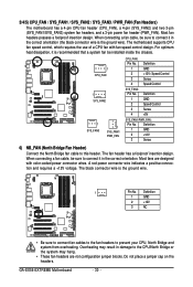
...GND 2 +12V / Speed Control 3 Sense 4 Speed Control SYS_FAN2: Pin No. Do not place a jumper cap on the headers. GA-EX58-EXTREME Motherboard - 30 - Most fan headers possess a foolproof insertion design. Most fans are not configuration jumper blocks. 3/4/5) CPU_FAN / SYS_FAN1 / SYS_FAN2 / SYS_FAN3 .../ PWR_FAN (Fan Headers) The motherboard has a 4-pin CPU fan header (CPU_FAN), a 4-pin (SYS_FAN2) and two 3-pin (SYS_FAN1/SYS_FAN3) system fan headers, and a 3-pin...
...GND 2 +12V / Speed Control 3 Sense 4 Speed Control SYS_FAN2: Pin No. Do not place a jumper cap on the headers. GA-EX58-EXTREME Motherboard - 30 - Most fan headers possess a foolproof insertion design. Most fans are not configuration jumper blocks. 3/4/5) CPU_FAN / SYS_FAN1 / SYS_FAN2 / SYS_FAN3 .../ PWR_FAN (Fan Headers) The motherboard has a 4-pin CPU fan header (CPU_FAN), a 4-pin (SYS_FAN2) and two 3-pin (SYS_FAN1/SYS_FAN3) system fan headers, and a 3-pin...
Manual
Page 32
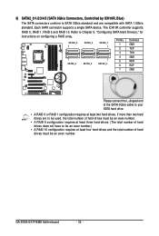
... number of hard drives does not have to Chapter 5, "Configuring SATA Hard Drive(s)," for instructions on configuring a RAID array. Refer to be an even number. GA-EX58-EXTREME Motherboard - 32 - The ICH10R controller supports RAID 0, RAID 1, RAID 5 and RAID 10. If more than two hard drives are compatible with SATA 1.5Gb/s standard. Each SATA...
... number of hard drives does not have to Chapter 5, "Configuring SATA Hard Drive(s)," for instructions on configuring a RAID array. Refer to be an even number. GA-EX58-EXTREME Motherboard - 32 - The ICH10R controller supports RAID 0, RAID 1, RAID 5 and RAID 10. If more than two hard drives are compatible with SATA 1.5Gb/s standard. Each SATA...

Manual
Page 34
... or writing data. • RES (Reset Switch, Green): Connects to the reset switch on the chassis front panel. You may differ by issuing a beep code. GA-EX58-EXTREME Motherboard - 34 - The S0 On LED is on when the system is detected at system startup. One single short beep will be heard if no problem...
... or writing data. • RES (Reset Switch, Green): Connects to the reset switch on the chassis front panel. You may differ by issuing a beep code. GA-EX58-EXTREME Motherboard - 34 - The S0 On LED is on when the system is detected at system startup. One single short beep will be heard if no problem...
Manual
Page 36
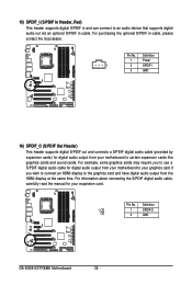
... audio cable (provided by expansion cards) for your motherboard to the graphics card and have digital audio output from your expansion card. For purchasing the optional S/PDIF in cable. Pin No. Definition 1 1 SPDIFO 2 GND GA-EX58-EXTREME Motherboard - 36 - For example, some graphics cards may... require you to use a S/PDIF digital audio cable for digital audio output from your motherboard to your graphics card if you wish to connect an HDMI...
... audio cable (provided by expansion cards) for your motherboard to the graphics card and have digital audio output from your expansion card. For purchasing the optional S/PDIF in cable. Pin No. Definition 1 1 SPDIFO 2 GND GA-EX58-EXTREME Motherboard - 36 - For example, some graphics cards may... require you to use a S/PDIF digital audio cable for digital audio output from your motherboard to your graphics card if you wish to connect an HDMI...
Manual
Page 38
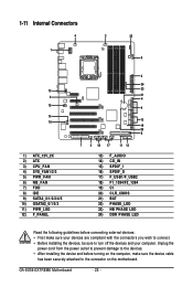
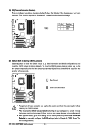
... load factory defaults (select Load Optimized Defaults) or manually configure the BIOS settings (refer to touch the two pins for BIOS configurations). GA-EX58-EXTREME Motherboard - 38 - To clear the CMOS values, place a jumper cap on your computer and unplug the power cord from the jumper. ...19) CI (Chassis Intrusion Header) This motherboard provides a chassis detection feature that detects if the chassis cover has been removed. date information and BIOS configurations) and reset the CMOS...
... load factory defaults (select Load Optimized Defaults) or manually configure the BIOS settings (refer to touch the two pins for BIOS configurations). GA-EX58-EXTREME Motherboard - 38 - To clear the CMOS values, place a jumper cap on your computer and unplug the power cord from the jumper. ...19) CI (Chassis Intrusion Header) This motherboard provides a chassis detection feature that detects if the chassis cover has been removed. date information and BIOS configurations) and reset the CMOS...

Manual
Page 40
The higher the North Bridge loading, the more the number of lighted LEDs. GA-EX58-EXTREME Motherboard - 40 - 23) NB PHASE LED The number of lighted LEDs indicates the memory loading. The higher the memory loading, the more the number of lighted LEDs. 24) DDR PHASE LED The number of lighted LEDs indicates the North Bridge loading.
The higher the North Bridge loading, the more the number of lighted LEDs. GA-EX58-EXTREME Motherboard - 40 - 23) NB PHASE LED The number of lighted LEDs indicates the memory loading. The higher the memory loading, the more the number of lighted LEDs. 24) DDR PHASE LED The number of lighted LEDs indicates the North Bridge loading.
Manual
Page 42
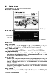
... If you to set the first boot device without having to access the Q-Flash utility in Boot Menu. GA-EX58-EXTREME Motherboard - 42 - 2-1 Startup Screen The following screens may appear when the computer boots. Motherboard Model BIOS Version EX58-EXTREME F1b . . . . : BIOS Setup : XpressRecovery2 : Boot Menu : Qflash 10/21/2008-X58-ICH10-7A89QG02C-00 Function Keys Function...
... If you to set the first boot device without having to access the Q-Flash utility in Boot Menu. GA-EX58-EXTREME Motherboard - 42 - 2-1 Startup Screen The following screens may appear when the computer boots. Motherboard Model BIOS Version EX58-EXTREME F1b . . . . : BIOS Setup : XpressRecovery2 : Boot Menu : Qflash 10/21/2008-X58-ICH10-7A89QG02C-00 Function Keys Function...


