
Manual
Page 1
GA-EP45-UD3 LGA775 socket motherboard for Intel® Core™ processor family/ Intel® Pentium® processor family/Intel® Celeron® processor family User's Manual Rev. 1101 12ME-EP45U3-1101R
GA-EP45-UD3 LGA775 socket motherboard for Intel® Core™ processor family/ Intel® Pentium® processor family/Intel® Celeron® processor family User's Manual Rev. 1101 12ME-EP45U3-1101R

Manual
Page 2
Motherboard GA-EP45-UD3 Sept. 30, 2008 Motherboard GA-EP45-UD3 Sept. 30, 2008
Motherboard GA-EP45-UD3 Sept. 30, 2008 Motherboard GA-EP45-UD3 Sept. 30, 2008

Manual
Page 3
..."REV: X.X." For product-related information, check on our website at: http://www.gigabyte.com.tw Identifying Your Motherboard Revision The revision number on your motherboard revision before updating motherboard BIOS, drivers, or when looking for technical information. Changes to the specifications and features...BYTE TECHNOLOGY CO., LTD. All rights reserved. The trademarks mentioned in the use GIGABYTE's unique features, read or download the information on/from the Support&Downloads\Motherboard\Technology Guide page on how to their respective owners. For detailed product information, ...
..."REV: X.X." For product-related information, check on our website at: http://www.gigabyte.com.tw Identifying Your Motherboard Revision The revision number on your motherboard revision before updating motherboard BIOS, drivers, or when looking for technical information. Changes to the specifications and features...BYTE TECHNOLOGY CO., LTD. All rights reserved. The trademarks mentioned in the use GIGABYTE's unique features, read or download the information on/from the Support&Downloads\Motherboard\Technology Guide page on how to their respective owners. For detailed product information, ...

Manual
Page 4
Table of Contents Box Contents...6 Optional Items...6 GA-EP45-UD3 Motherboard Layout 7 Block Diagram...8 Chapter 1 Hardware Installation 9 1-1 Installation Precautions 9 1-2 Product Specifications 10 1-3 Installing the CPU and CPU Cooler 13 1-3-1 Installing the CPU 13 1-3-2 Installing the CPU ...
Table of Contents Box Contents...6 Optional Items...6 GA-EP45-UD3 Motherboard Layout 7 Block Diagram...8 Chapter 1 Hardware Installation 9 1-1 Installation Precautions 9 1-2 Product Specifications 10 1-3 Installing the CPU and CPU Cooler 13 1-3-1 Installing the CPU 13 1-3-2 Installing the CPU ...

Manual
Page 6
.... 12CF1-2SERPW-0*R) S/PDIF In cable (Part No. 12CR1-1SPDIN-0*R) COM port cable (Part No. 12CF1-1CM001-3*R) LPT port cable (Part No. 12CF1-1LP001-0*R) - 6 - Box Contents GA-EP45-UD3 motherboard Motherboard driver disk User's Manual Quick Installation Guide One IDE cable Two SATA 3Gb/s cables I/O Shield • The box contents above are subject to change without...
.... 12CF1-2SERPW-0*R) S/PDIF In cable (Part No. 12CR1-1SPDIN-0*R) COM port cable (Part No. 12CF1-1CM001-3*R) LPT port cable (Part No. 12CF1-1LP001-0*R) - 6 - Box Contents GA-EP45-UD3 motherboard Motherboard driver disk User's Manual Quick Installation Guide One IDE cable Two SATA 3Gb/s cables I/O Shield • The box contents above are subject to change without...

Manual
Page 7
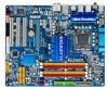
GA-EP45-UD3 Motherboard Layout KB_MS R_SPDIF USB_1394_2 ATX_12V_2X4 USB_1394_1 R_USB PWR_FAN LGA775 CPU_FAN PHASE_LED ATX GA-EP45-UD3 USB_LAN AUDIO F_AUDIO SYS_FAN1 PCIEX1_1 RTL8111C PCIEX1_2 PCIEX16 CODEC PCIEX1_3 BAT SPDIF_O CI PCI1 IT8718 PCI2 SPDIF_I PCI3 CD_IN Intel® P45 IDE SYS_FAN2 Intel® ICH10 GIGABYTE SATA2 SATA2_4 SATA2_2 SATA2_0 TSB43AB23 FDD SATA2_5 SATA2_3 SATA2_1 M_BIOS B_BIOS PWR_LED CLR_CMOS COMA LPT F1_1394 F_USB2 F_USB1 F_PANEL DDR2_1 DDR2_2 DDR2_3 DDR2_4 GSATA2_0 GSATA2_1 - 7 -
GA-EP45-UD3 Motherboard Layout KB_MS R_SPDIF USB_1394_2 ATX_12V_2X4 USB_1394_1 R_USB PWR_FAN LGA775 CPU_FAN PHASE_LED ATX GA-EP45-UD3 USB_LAN AUDIO F_AUDIO SYS_FAN1 PCIEX1_1 RTL8111C PCIEX1_2 PCIEX16 CODEC PCIEX1_3 BAT SPDIF_O CI PCI1 IT8718 PCI2 SPDIF_I PCI3 CD_IN Intel® P45 IDE SYS_FAN2 Intel® ICH10 GIGABYTE SATA2 SATA2_4 SATA2_2 SATA2_0 TSB43AB23 FDD SATA2_5 SATA2_3 SATA2_1 M_BIOS B_BIOS PWR_LED CLR_CMOS COMA LPT F1_1394 F_USB2 F_USB1 F_PANEL DDR2_1 DDR2_2 DDR2_3 DDR2_4 GSATA2_0 GSATA2_1 - 7 -

Manual
Page 9
...use of the product, please consult a certified computer technician. - 9 - Hardware Installation Chapter 1 Hardware Installation 1-1 Installation Precautions The motherboard contains numerous delicate electronic circuits and components which can lead to damage to system components as well as physical harm to the user.... shielding container. • Before unplugging the power supply cable from the power outlet before installing or removing the motherboard or other hardware components. • When connecting hardware components to the internal connectors on the computer power during ...
...use of the product, please consult a certified computer technician. - 9 - Hardware Installation Chapter 1 Hardware Installation 1-1 Installation Precautions The motherboard contains numerous delicate electronic circuits and components which can lead to damage to system components as well as physical harm to the user.... shielding container. • Before unplugging the power supply cable from the power outlet before installing or removing the motherboard or other hardware components. • When connecting hardware components to the internal connectors on the computer power during ...

Manual
Page 10
... Express x1 slots w 3 x PCI slots Storage Interface w South Bridge: - 6 x SATA 3Gb/s connectors (SATA2_0, SATA2_1, SATA2_2, SATA2_3, SATA2_4, SATA2_5) supporting up to 6 SATA 3Gb/s devices w GIGABYTE SATA2 chip: - 1 x IDE connector supporting ATA-133/100/66/33 and up to 2 IDE devices - 2 x SATA 3Gb/s connectors (GSATA2_0, GSATA2_1) supporting up to 1 floppy disk... TSB43AB23 chip w Up to 3 IEEE 1394a ports (2 on the back panel, 4 via the IEEE 1394a bracket connected to the internal IEEE 1394a header) GA-EP45-UD3 Motherboard - 10 -
... Express x1 slots w 3 x PCI slots Storage Interface w South Bridge: - 6 x SATA 3Gb/s connectors (SATA2_0, SATA2_1, SATA2_2, SATA2_3, SATA2_4, SATA2_5) supporting up to 6 SATA 3Gb/s devices w GIGABYTE SATA2 chip: - 1 x IDE connector supporting ATA-133/100/66/33 and up to 2 IDE devices - 2 x SATA 3Gb/s connectors (GSATA2_0, GSATA2_1) supporting up to 1 floppy disk... TSB43AB23 chip w Up to 3 IEEE 1394a ports (2 on the back panel, 4 via the IEEE 1394a bracket connected to the internal IEEE 1394a header) GA-EP45-UD3 Motherboard - 10 -
Manual
Page 12
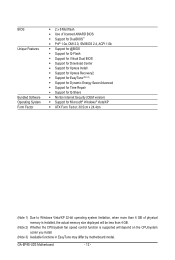
GA-EP45-UD3 Motherboard - 12 - BIOS Unique Features Bundled Software Operating System Form Factor w 2 x 8 Mbit flash w Use of licensed AWARD BIOS w Support for DualBIOS™ w PnP 1.0a, DMI 2.0, SM ... CPU/system fan speed control function is supported will depend on the CPU/system cooler you install. (Note 3) Available functions in EasyTune may differ by motherboard model.
GA-EP45-UD3 Motherboard - 12 - BIOS Unique Features Bundled Software Operating System Form Factor w 2 x 8 Mbit flash w Use of licensed AWARD BIOS w Support for DualBIOS™ w PnP 1.0a, DMI 2.0, SM ... CPU/system fan speed control function is supported will depend on the CPU/system cooler you install. (Note 3) Available functions in EasyTune may differ by motherboard model.

Manual
Page 13
... 1-3-1 Installing the CPU A. age of the CPU. It is not installed, otherwise overheating and dam- Hardware Installation Locate the alignment keys on the motherboard CPU socket and the notches on the CPU. LGA775 CPU Socket Alignment Key LGA775 CPU Alignment Key Pin One Corner of the CPU. • Do...and unplug the power cord from the power outlet before you begin to install the CPU: • Make sure that the motherboard supports the CPU. (Go to GIGABYTE's website for the peripherals. The CPU cannot be set the frequency beyond hardware specifications since it does not meet the standard ...
... 1-3-1 Installing the CPU A. age of the CPU. It is not installed, otherwise overheating and dam- Hardware Installation Locate the alignment keys on the motherboard CPU socket and the notches on the CPU. LGA775 CPU Socket Alignment Key LGA775 CPU Alignment Key Pin One Corner of the CPU. • Do...and unplug the power cord from the power outlet before you begin to install the CPU: • Make sure that the motherboard supports the CPU. (Go to GIGABYTE's website for the peripherals. The CPU cannot be set the frequency beyond hardware specifications since it does not meet the standard ...

Manual
Page 14
..., always replace the protective socket cover when the CPU is properly inserted, replace the load plate and push the CPU socket lever back into the motherboard CPU socket. Align the CPU pin one marking (triangle) with the pin one corner of the CPU socket (or you may align the CPU notches... index fingers. Step 5: Once the CPU is not installed.) Step 4: Hold the CPU with the socket alignment keys) and gently insert the CPU into position. GA-EP45-UD3 Motherboard - 14 - CPU Socket Lever Step 1: Completely raise the CPU socket lever.
..., always replace the protective socket cover when the CPU is properly inserted, replace the load plate and push the CPU socket lever back into the motherboard CPU socket. Align the CPU pin one marking (triangle) with the pin one corner of the CPU socket (or you may align the CPU notches... index fingers. Step 5: Once the CPU is not installed.) Step 4: Hold the CPU with the socket alignment keys) and gently insert the CPU into position. GA-EP45-UD3 Motherboard - 14 - CPU Socket Lever Step 1: Completely raise the CPU socket lever.

Manual
Page 15
...for instructions on installing the cooler.) Step 5: After the installation, check the back of the CPU cooler to the CPU fan header (CPU_FAN) on the motherboard. Inadequately removing the CPU cooler may adhere to the CPU. Hardware Installation Step 4: You should hear a "click" when pushing down on the male ...shows, the installation is to install.) Step 3: Place the cooler atop the CPU, aligning the four push pins through the pin holes on the motherboard. Direction of the Arrow Sign on the Male Push Pin Male Push Pin The Top of Female Push Pin Female Push Pin Step 2: Before ...
...for instructions on installing the cooler.) Step 5: After the installation, check the back of the CPU cooler to the CPU fan header (CPU_FAN) on the motherboard. Inadequately removing the CPU cooler may adhere to the CPU. Hardware Installation Step 4: You should hear a "click" when pushing down on the male ...shows, the installation is to install.) Step 3: Place the cooler atop the CPU, aligning the four push pins through the pin holes on the motherboard. Direction of the Arrow Sign on the Male Push Pin Male Push Pin The Top of Female Push Pin Female Push Pin Step 2: Before ...

Manual
Page 16
...detect the specifications and capacity of the memory. DS/SS - - If you begin to install the memory: • Make sure that the motherboard supports the memory. It is installed. 2. DS/SS Four Modules DS/SS DS/SS DS/SS DS/SS (SS=Single-Sided, DS=Double... memory bandwidth. Intel Flex Memory Technology offers greater flexibility to upgrade by allowing different memory sizes to be used . (Go to GIGABYTE's website for optimum performance. GA-EP45-UD3 Motherboard - 16 - DS/SS - - - - The four DDR2 memory sockets are divided into two channels and each channel has two...
...detect the specifications and capacity of the memory. DS/SS - - If you begin to install the memory: • Make sure that the motherboard supports the memory. It is installed. 2. DS/SS Four Modules DS/SS DS/SS DS/SS DS/SS (SS=Single-Sided, DS=Double... memory bandwidth. Intel Flex Memory Technology offers greater flexibility to upgrade by allowing different memory sizes to be used . (Go to GIGABYTE's website for optimum performance. GA-EP45-UD3 Motherboard - 16 - DS/SS - - - - The four DDR2 memory sockets are divided into two channels and each channel has two...

Manual
Page 17
..., make sure to turn off the computer and unplug the power cord from the power outlet to prevent damage to install DDR2 DIMMs on this motherboard. Notch DDR2 DIMM A DDR2 memory module has a notch, so it vertically into place when the memory module is securely inserted. - 17 - Spread the retaining clips...
..., make sure to turn off the computer and unplug the power cord from the power outlet to prevent damage to install DDR2 DIMMs on this motherboard. Notch DDR2 DIMM A DDR2 memory module has a notch, so it vertically into place when the memory module is securely inserted. - 17 - Spread the retaining clips...

Manual
Page 18
... the expansion card. Locate an expansion slot that came with the expansion card in your expansion card in the slot. 3. GA-EP45-UD3 Motherboard - 18 - Align the card with a screw. 5. Example: Installing and Removing a PCI Express Graphics Card: • Installing a Graphics Card: Gently push down on the slot and ...
... the expansion card. Locate an expansion slot that came with the expansion card in your expansion card in the slot. 3. GA-EP45-UD3 Motherboard - 18 - Align the card with a screw. 5. Example: Installing and Removing a PCI Express Graphics Card: • Installing a Graphics Card: Gently push down on the slot and ...

Manual
Page 19
... device. The following describes the states of the LAN port LEDs. Before using this feature, ensure that your device and then remove it from the motherboard. • When removing the cable, pull it side to side to prevent an electrical short inside the cable connector. - 19 - Do not rock it straight...
... device. The following describes the states of the LAN port LEDs. Before using this feature, ensure that your device and then remove it from the motherboard. • When removing the cable, pull it side to side to prevent an electrical short inside the cable connector. - 19 - Do not rock it straight...

Manual
Page 20
... via the audio software. Only microphones still MUST be used to the instructions on setting up a 2/4/5.1/7.1-channel audio con- figuration in Chapter 5, "Configuring 2/4/5.1/7.1-Channel Audio." GA-EP45-UD3 Motherboard - 20 -
... via the audio software. Only microphones still MUST be used to the instructions on setting up a 2/4/5.1/7.1-channel audio con- figuration in Chapter 5, "Configuring 2/4/5.1/7.1-Channel Audio." GA-EP45-UD3 Motherboard - 20 -

Manual
Page 21
...) F_USB1/F_USB2 17) F1_1394 18) LPT 19) COMA 20) CI 21) CLR_CMOS 22) BAT 23) PHASE LED Read the following guidelines before turning on the motherboard. - 21 -
...) F_USB1/F_USB2 17) F1_1394 18) LPT 19) COMA 20) CI 21) CLR_CMOS 22) BAT 23) PHASE LED Read the following guidelines before turning on the motherboard. - 21 -

Manual
Page 22
... a power supply providing a 2x4 12V and a 2x12 power connector, remove the protective covers from the 12V power connector and the main power connector on the motherboard. Do not insert the power supply cables into pins under the protective covers when using a power supply providing a 2x2 12V and a 2x10 power connector. 5 8 .../Off) GND GND GND -5V +5V +5V +5V (Only for 2x12-pin ATX) GND (Only for 2x4-pin 12V) 7 +12V 8 +12V 12 24 1 13 ATX GA-EP45-UD3 Motherboard ATX: Pin No. 1 2 3 4 5 6 7 8 9 10 11 12 Definition Pin No. 3.3V 13 3.3V 14 GND 15 +5V 16 GND 17 +5V 18 GND 19...
... a power supply providing a 2x4 12V and a 2x12 power connector, remove the protective covers from the 12V power connector and the main power connector on the motherboard. Do not insert the power supply cables into pins under the protective covers when using a power supply providing a 2x2 12V and a 2x10 power connector. 5 8 .../Off) GND GND GND -5V +5V +5V +5V (Only for 2x12-pin ATX) GND (Only for 2x4-pin 12V) 7 +12V 8 +12V 12 24 1 13 ATX GA-EP45-UD3 Motherboard ATX: Pin No. 1 2 3 4 5 6 7 8 9 10 11 12 Definition Pin No. 3.3V 13 3.3V 14 GND 15 +5V 16 GND 17 +5V 18 GND 19...

Manual
Page 23
.../PWR_FAN SYS_FAN1/PWR_FAN: Pin No. The pin 1 of the cable is recommended that a system fan be installed inside the chassis. The motherboard supports CPU fan speed control, which requires the use of floppy disk drives supported are not configuration jumper blocks. Definition 1 GND 1 2... floppy disk drive, be sure to locate pin 1 of different color. 33 1 34 2 - 23 - 3/4/5) CPU_FAN/SYS_FAN1/SYS_FAN2/PWR_FAN (Fan Headers) The motherboard has a 4-pin CPU fan header (CPU_FAN), a 4-pin (SYS_FAN2) and a 3-pin (SYS_FAN1) system fan headers, and a 3-pin power fan header (PWR_FAN...
.../PWR_FAN SYS_FAN1/PWR_FAN: Pin No. The pin 1 of the cable is recommended that a system fan be installed inside the chassis. The motherboard supports CPU fan speed control, which requires the use of floppy disk drives supported are not configuration jumper blocks. Definition 1 GND 1 2... floppy disk drive, be sure to locate pin 1 of different color. 33 1 34 2 - 23 - 3/4/5) CPU_FAN/SYS_FAN1/SYS_FAN2/PWR_FAN (Fan Headers) The motherboard has a 4-pin CPU fan header (CPU_FAN), a 4-pin (SYS_FAN2) and a 3-pin (SYS_FAN1) system fan headers, and a 3-pin power fan header (PWR_FAN...


