Manual
Page 3
.... No part of GIGABYTE. Example: Copyright © 2009 GIGA-BYTE TECHNOLOGY CO., LTD. For instructions on how to the specifications and features in this manual may be reproduced, copied, translated, transmitted, or published in the use GIGABYTE's unique features, read the User's Manual. For detailed product information, carefully read or download the information on/from the Support&Downloads\Motherboard\Technology Guide page on your motherboard revision before updating motherboard BIOS, drivers, or...
.... No part of GIGABYTE. Example: Copyright © 2009 GIGA-BYTE TECHNOLOGY CO., LTD. For instructions on how to the specifications and features in this manual may be reproduced, copied, translated, transmitted, or published in the use GIGABYTE's unique features, read the User's Manual. For detailed product information, carefully read or download the information on/from the Support&Downloads\Motherboard\Technology Guide page on your motherboard revision before updating motherboard BIOS, drivers, or...
Manual
Page 4
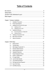
Table of Contents Box Contents...6 Optional Items...6 GA-EP41T-UD3L Motherboard Layout 7 Block Diagram...8 Chapter 1 Hardware Installation 9 1-1 Installation Precautions 9 1-2 Product Specifications 10 1-3 Installing the CPU and CPU Cooler 13 1-3-1 Installing the CPU 13 1-3-2 Installing the CPU Cooler 15 1-4 Installing the Memory 16 1-4-1 Dual Channel Memory Configuration 16 1-4-2 Installing a Memory 17 1-5 Installing an Expansion Card 18 1-6 Back Panel Connectors 19 1-7 Internal Connectors 21 Chapter 2 BIOS Setup 31 2-1 Startup Screen 32 2-2 The Main Menu 33 2-3 MB Intelligent...
Table of Contents Box Contents...6 Optional Items...6 GA-EP41T-UD3L Motherboard Layout 7 Block Diagram...8 Chapter 1 Hardware Installation 9 1-1 Installation Precautions 9 1-2 Product Specifications 10 1-3 Installing the CPU and CPU Cooler 13 1-3-1 Installing the CPU 13 1-3-2 Installing the CPU Cooler 15 1-4 Installing the Memory 16 1-4-1 Dual Channel Memory Configuration 16 1-4-2 Installing a Memory 17 1-5 Installing an Expansion Card 18 1-6 Back Panel Connectors 19 1-7 Internal Connectors 21 Chapter 2 BIOS Setup 31 2-1 Startup Screen 32 2-2 The Main Menu 33 2-3 MB Intelligent...

Manual
Page 11
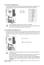
... 24-pin ATX main power connector 1 x 4-pin ATX 12V power connector 1 x floppy disk drive connector 1 x IDE connector 4 x SATA 3Gb/s connectors 1 x CPU fan header 2 x system fan headers 1 x power fan header 1 x front panel header 1 x front panel audio header 1 x CD In connector 1 x S/PDIF In header 1 x S/PDIF Out header 2 x USB 2.0/1.1 headers 1 x clearing CMOS jumper 1 x PS/2 keyboard port 1 x PS/2 mouse port 1 x parallel port 1 x coaxial S/PDIF Out connector 1 x optical S/PDIF Out connector 1 x serial port 4 x USB 2.0/1.1 ports 1 x RJ-45 port 6 x audio jacks (Center/Subwoofer Speaker Out/Rear...
... 24-pin ATX main power connector 1 x 4-pin ATX 12V power connector 1 x floppy disk drive connector 1 x IDE connector 4 x SATA 3Gb/s connectors 1 x CPU fan header 2 x system fan headers 1 x power fan header 1 x front panel header 1 x front panel audio header 1 x CD In connector 1 x S/PDIF In header 1 x S/PDIF Out header 2 x USB 2.0/1.1 headers 1 x clearing CMOS jumper 1 x PS/2 keyboard port 1 x PS/2 mouse port 1 x parallel port 1 x coaxial S/PDIF Out connector 1 x optical S/PDIF Out connector 1 x serial port 4 x USB 2.0/1.1 ports 1 x RJ-45 port 6 x audio jacks (Center/Subwoofer Speaker Out/Rear...
Manual
Page 16
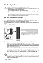
... enabling Dual Channel mode with two or four memory modules, it on the DDR3_1 and DDR3_3 sockets. (Go to insert the memory, switch the direction. 1-4-1 Dual Channel Memory Configuration This motherboard provides four DDR3 memory sockets and supports Dual Channel Technology. Because of the same capacity, brand, speed, and chips be used and installed in the same colored DDR3 sockets for the latest memory support list.) • Always turn off the computer and unplug the power cord from the power...
... enabling Dual Channel mode with two or four memory modules, it on the DDR3_1 and DDR3_3 sockets. (Go to insert the memory, switch the direction. 1-4-1 Dual Channel Memory Configuration This motherboard provides four DDR3 memory sockets and supports Dual Channel Technology. Because of the same capacity, brand, speed, and chips be used and installed in the same colored DDR3 sockets for the latest memory support list.) • Always turn off the computer and unplug the power cord from the power...
Manual
Page 18
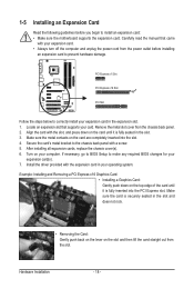
... to BIOS Setup to the chassis back panel with your expansion card. • Always turn off the computer and unplug the power cord from the power outlet before you begin to correctly install your expansion card(s). 7. Example: Installing and Removing a PCI Express x16 Graphics Card: • Installing a Graphics Card: Gently push down on the card until it is securely seated in the expansion slot. 1. Remove the metal slot cover from the slot. 1-5 Installing an Expansion Card...
... to BIOS Setup to the chassis back panel with your expansion card. • Always turn off the computer and unplug the power cord from the power outlet before you begin to correctly install your expansion card(s). 7. Example: Installing and Removing a PCI Express x16 Graphics Card: • Installing a Graphics Card: Gently push down on the card until it is securely seated in the expansion slot. 1. Remove the metal slot cover from the slot. 1-5 Installing an Expansion Card...

Manual
Page 23
...2 +12V / Speed Control CPU_FAN 3 Sense 4 Speed Control SYS_FAN2: Pin No. Definition 1 GND 2 +12V 3 Sense • Be sure to connect fan cables to the fan headers to locate pin 1 of floppy disk drives supported are not configuration jumper blocks. When connecting a fan cable, be installed inside the chassis. 3/4/5) CPU_FAN/SYS_FAN1/SYS_FAN2/PWR_FAN (Fan Headers) The motherboard has a 4-pin CPU fan header (CPU_FAN), a 4-pin (SYS_FAN2) and a 3-pin (SYS_FAN1) system fan headers, and a 3-pin power fan header (PWR_FAN). For optimum heat dissipation, it is used to connect it in...
...2 +12V / Speed Control CPU_FAN 3 Sense 4 Speed Control SYS_FAN2: Pin No. Definition 1 GND 2 +12V 3 Sense • Be sure to connect fan cables to the fan headers to locate pin 1 of floppy disk drives supported are not configuration jumper blocks. When connecting a fan cable, be installed inside the chassis. 3/4/5) CPU_FAN/SYS_FAN1/SYS_FAN2/PWR_FAN (Fan Headers) The motherboard has a 4-pin CPU fan header (CPU_FAN), a 4-pin (SYS_FAN2) and a 3-pin (SYS_FAN1) system fan headers, and a 3-pin power fan header (PWR_FAN). For optimum heat dissipation, it is used to connect it in...
Manual
Page 28
... short the two pins or use a metal object like a screwdriver to clear the CMOS values (e.g. Failure to do so may cause damage to the motherboard. • After system restart, go to BIOS Setup to load factory defaults (select Load Optimized Defaults) or manually configure the BIOS settings (refer to turn off your computer, be sure to Chapter 2, "BIOS Setup," for a few seconds. Pin No. date information and BIOS configurations) and reset the CMOS values to USB 2.0/1.1 specification...
... short the two pins or use a metal object like a screwdriver to clear the CMOS values (e.g. Failure to do so may cause damage to the motherboard. • After system restart, go to BIOS Setup to load factory defaults (select Load Optimized Defaults) or manually configure the BIOS settings (refer to turn off your computer, be sure to Chapter 2, "BIOS Setup," for a few seconds. Pin No. date information and BIOS configurations) and reset the CMOS values to USB 2.0/1.1 specification...

Manual
Page 31
... BIOS Setup menu options, you not flash the BIOS. If this occurs, try to clear the CMOS values and reset the board to default values. (Refer to the "Load Optimized Defaults" section in Chapter 1 for how to Chapter 5, "Troubleshooting," for the beep codes description. • It is a Windows-based utility that allows the user to modify basic system configuration settings or to prevent system instability or other unexpected results. BIOS Setup To upgrade the BIOS, use...
... BIOS Setup menu options, you not flash the BIOS. If this occurs, try to clear the CMOS values and reset the board to default values. (Refer to the "Load Optimized Defaults" section in Chapter 1 for how to Chapter 5, "Troubleshooting," for the beep codes description. • It is a Windows-based utility that allows the user to modify basic system configuration settings or to prevent system instability or other unexpected results. BIOS Setup To upgrade the BIOS, use...
Manual
Page 32
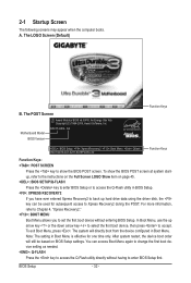
... will still be used for one time only. After system restart, the device boot order will directly boot from the device configured in Boot Menu. A. BIOS Setup - 32 - Motherboard Model BIOS Version EP41T-UD3L E4 . . . . : BIOS Setup : XpressRecovery2 : Boot Menu : Qflash 09/21/2009-G41-ICH7-6A79PG05C-00 Function Keys Function Keys Function Keys: : POST SCREEN Press the key to access the Q-Flash utility directly without entering BIOS Setup. Note: The setting in BIOS Setup. : XPRESS RECOVERY2 If you to set the first boot device without having to...
... will still be used for one time only. After system restart, the device boot order will directly boot from the device configured in Boot Menu. A. BIOS Setup - 32 - Motherboard Model BIOS Version EP41T-UD3L E4 . . . . : BIOS Setup : XpressRecovery2 : Boot Menu : Qflash 09/21/2009-G41-ICH7-6A79PG05C-00 Function Keys Function Keys Function Keys: : POST SCREEN Press the key to access the Q-Flash utility directly without entering BIOS Setup. Note: The setting in BIOS Setup. : XPRESS RECOVERY2 If you to set the first boot device without having to...

Manual
Page 34
..., hard drive types, floppy disk drive types, and the type of errors that stop the system boot, etc. Advanced BIOS Features Use this menu to configure the device boot order, advanced features available on the CPU, and the primary display adapter. Integrated Peripherals Use this menu to configure all peripheral devices, such as IDE, SATA, USB, integrated audio, and integrated LAN, etc. Power Management Setup Use this menu to see information about autodetected system/CPU temperature, system voltage and fan speed, etc. Load...
..., hard drive types, floppy disk drive types, and the type of errors that stop the system boot, etc. Advanced BIOS Features Use this menu to configure the device boot order, advanced features available on the CPU, and the primary display adapter. Integrated Peripherals Use this menu to configure all peripheral devices, such as IDE, SATA, USB, integrated audio, and integrated LAN, etc. Power Management Setup Use this menu to see information about autodetected system/CPU temperature, system voltage and fan speed, etc. Load...

Manual
Page 35
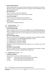
...Host Clock Control x CPU Host Frequency (Mhz) PCI Express Frequency (Mhz) >>>>> Advanced Clock Control [Disabled] 200 [Auto] ******** DRAM Performance Control ******** Performance Enhance [Standard] (G)MCH Frequency Latch [Auto] System Memory Multiplier (SPD) [Auto] Memory Frequency (Mhz) 1333 800 DRAM Timing Selectable (SPD) [Auto] >>>>> Standard Timing Control Move Enter: Select F5: Previous Values +/-/PU/PD: Value F10: Save F6: Fail-Safe Defaults ESC: Exit F1: General Help F7: Optimized Defaults CMOS Setup Utility-Copyright (C) 1984-2009 Award Software...
...Host Clock Control x CPU Host Frequency (Mhz) PCI Express Frequency (Mhz) >>>>> Advanced Clock Control [Disabled] 200 [Auto] ******** DRAM Performance Control ******** Performance Enhance [Standard] (G)MCH Frequency Latch [Auto] System Memory Multiplier (SPD) [Auto] Memory Frequency (Mhz) 1333 800 DRAM Timing Selectable (SPD) [Auto] >>>>> Standard Timing Control Move Enter: Select F5: Previous Values +/-/PU/PD: Value F10: Save F6: Fail-Safe Defaults ESC: Exit F1: General Help F7: Optimized Defaults CMOS Setup Utility-Copyright (C) 1984-2009 Award Software...
Manual
Page 36
... sets the PCIe clock frequency to standard 100 MHz. (Default: Auto) ******** DRAM Performance Control ******** Performance Enhance Allows the system to manually set the CPU host frequency. BIOS Setup - 36 - CPU Frequency Displays the current operating CPU frequency. ******** Clock Chip Control Standard Clock Control CPU Host Clock Control Enables or disables the control of the graphics chip and memory. The adjustable range is installed. Enabled will allow for 20 seconds to allow the CPU Host Frequency item below to 150 MHz. Note: If your system fails to boot after overclocking...
... sets the PCIe clock frequency to standard 100 MHz. (Default: Auto) ******** DRAM Performance Control ******** Performance Enhance Allows the system to manually set the CPU host frequency. BIOS Setup - 36 - CPU Frequency Displays the current operating CPU frequency. ******** Clock Chip Control Standard Clock Control CPU Host Clock Control Enables or disables the control of the graphics chip and memory. The adjustable range is installed. Enabled will allow for 20 seconds to allow the CPU Host Frequency item below to 150 MHz. Note: If your system fails to boot after overclocking...
Manual
Page 43
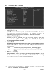
...enter BIOS Setup. First/Second/Third Boot Device Specifies the boot order from the installed hard drives. 2-5 Advanced BIOS Features CMOS Setup Utility-Copyright (C) 1984-2009 Award Software Advanced BIOS Features } Hard Disk Boot Priority First Boot Device Second Boot Device Third Boot Device Password Check HDD S.M.A.R.T. Press to accept. Options are: Floppy, LS120, Hard Disk, CDROM, ZIP, USB-FDD, USB-ZIP, USB-CDROM, USB-HDD, Legacy LAN, Disabled. HDD S.M.A.R.T. Setup A password is only required for entering the BIOS Setup program. (Default) System A password...
...enter BIOS Setup. First/Second/Third Boot Device Specifies the boot order from the installed hard drives. 2-5 Advanced BIOS Features CMOS Setup Utility-Copyright (C) 1984-2009 Award Software Advanced BIOS Features } Hard Disk Boot Priority First Boot Device Second Boot Device Third Boot Device Password Check HDD S.M.A.R.T. Press to accept. Options are: Floppy, LS120, Hard Disk, CDROM, ZIP, USB-FDD, USB-ZIP, USB-CDROM, USB-HDD, Legacy LAN, Disabled. HDD S.M.A.R.T. Setup A password is only required for entering the BIOS Setup program. (Default) System A password...
Manual
Page 46
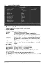
..., this option will be used simultaneously: two PATA devices plus two SATA devices. BIOS Setup - 46 - Ch.0 Master/Slave Sets the IDE channels to Ch. 0 Master/Slave. (Default) Ch.1 Master/Slave Sets the IDE channels to Azalia Codec Onboard H/W LAN Green LAN } SMART LAN Onboard LAN Boot ROM Onboard Serial Port 1 Onboard Parallel Port Parallel Port Mode USB 1.0 Controller USB 2.0 Controller USB Keyboard Function USB Mouse Function USB Storage Function [Enabled] [Auto] Ch.1 Master/Slave Ch.0 Master/Slave Disable [Auto] [Enabled] [Disabled...
..., this option will be used simultaneously: two PATA devices plus two SATA devices. BIOS Setup - 46 - Ch.0 Master/Slave Sets the IDE channels to Ch. 0 Master/Slave. (Default) Ch.1 Master/Slave Sets the IDE channels to Azalia Codec Onboard H/W LAN Green LAN } SMART LAN Onboard LAN Boot ROM Onboard Serial Port 1 Onboard Parallel Port Parallel Port Mode USB 1.0 Controller USB 2.0 Controller USB Keyboard Function USB Mouse Function USB Storage Function [Enabled] [Auto] Ch.1 Master/Slave Ch.0 Master/Slave Disable [Auto] [Enabled] [Disabled...

Manual
Page 47
... message will appear: Start detecting at Port..... Onboard H/W LAN Enables or disables the onboard LAN function. (Default: Enabled) If you wish to settings. Green LAN When the onboard LAN function and Green LAN are enabled, the system will only operate at Port..... If no cable problem is detected on the On-Chip SATA Mode and PATA IDE Set to install a 3rd party add-in Windows mode or when the LAN Boot ROM is connected or not. When LAN Cable Is Functioning Normally... Note...
... message will appear: Start detecting at Port..... Onboard H/W LAN Enables or disables the onboard LAN function. (Default: Enabled) If you wish to settings. Green LAN When the onboard LAN function and Green LAN are enabled, the system will only operate at Port..... If no cable problem is detected on the On-Chip SATA Mode and PATA IDE Set to install a 3rd party add-in Windows mode or when the LAN Boot ROM is connected or not. When LAN Cable Is Functioning Normally... Note...

Manual
Page 48
...and USB hard drives during the POST. (Default: Enabled) BIOS Setup - 48 - Options are : SPP (Standard Parallel Port) (default), EPP (Enhanced Parallel Port), ECP (Extended Capabilities Port), ECP+EPP. Note: Part 4-5 and Part 7-8 are : 378/IRQ7 (default), 278/IRQ5, 3BC/IRQ7, Disabled. USB 2.0 Controller Enables or disables the integrated USB 2.0 controller. (Default: Enabled) USB Keyboard Function Allows USB keyboard to be used in MS-DOS. (Default: Disabled) USB Mouse Function Allows USB mouse to be the approximate distance to activate the boot ROM integrated with the onboard LAN chip...
...and USB hard drives during the POST. (Default: Enabled) BIOS Setup - 48 - Options are : SPP (Standard Parallel Port) (default), EPP (Enhanced Parallel Port), ECP (Extended Capabilities Port), ECP+EPP. Note: Part 4-5 and Part 7-8 are : 378/IRQ7 (default), 278/IRQ5, 3BC/IRQ7, Disabled. USB 2.0 Controller Enables or disables the integrated USB 2.0 controller. (Default: Enabled) USB Keyboard Function Allows USB keyboard to be used in MS-DOS. (Default: Disabled) USB Mouse Function Allows USB mouse to be the approximate distance to activate the boot ROM integrated with the onboard LAN chip...
Manual
Page 52
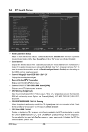
... system voltages. Check the fan condition or fan connection when this function. Auto lets the BIOS decide whether to enable this occurs. (Default: Disabled) CPU Smart FAN Control Enables or disables the CPU fan speed control function. If disabled, the CPU fan runs at different speed according to run at full speed. (Default: Auto) BIOS Setup - 52 - To clear the chassis intrusion status record, set Reset Case Open Status to Enabled, save the settings to the motherboard CI header. Current System/CPU Temperature Displays current system/CPU temperature. You can adjust the fan speed...
... system voltages. Check the fan condition or fan connection when this function. Auto lets the BIOS decide whether to enable this occurs. (Default: Disabled) CPU Smart FAN Control Enables or disables the CPU fan speed control function. If disabled, the CPU fan runs at different speed according to run at full speed. (Default: Auto) BIOS Setup - 52 - To clear the chassis intrusion status record, set Reset Case Open Status to Enabled, save the settings to the motherboard CI header. Current System/CPU Temperature Displays current system/CPU temperature. You can adjust the fan speed...
Manual
Page 64
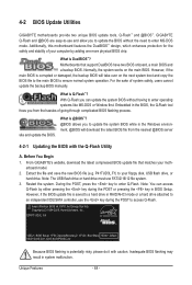
... the system. Inadequate BIOS flashing may result in RAID/AHCI mode or a hard drive attached to an independent IDE/SATA controller, use FAT32/16/12 file system. 3. Unique Features - 64 - Motherboards that matches your computer by either pressing the key during the POST to access Q-Flash. However, if the main BIOS is @BIOS™? @BIOS allows you to update the BIOS without having to your floppy disk, USB flash drive, or hard drive. Before You Begin 1. EP41T-UD3L E4 . . . . : BIOS Setup : XpressRecovery2 : Boot Menu : Qflash 09...
... the system. Inadequate BIOS flashing may result in RAID/AHCI mode or a hard drive attached to an independent IDE/SATA controller, use FAT32/16/12 file system. 3. Unique Features - 64 - Motherboards that matches your computer by either pressing the key during the POST to access Q-Flash. However, if the main BIOS is @BIOS™? @BIOS allows you to update the BIOS without having to your floppy disk, USB flash drive, or hard drive. Before You Begin 1. EP41T-UD3L E4 . . . . : BIOS Setup : XpressRecovery2 : Boot Menu : Qflash 09...

Manual
Page 65
... file to a floppy disk. Select the BIOS update file and press . Make sure the BIOS update file matches your motherboard model. Step 2: The process of Q-Flash, use the key during the POST to update BIOS?" Q-Flash Utility v2.13 Flash Type/Size MXIC 25L8005 1M Keep DMI Data Enable !L! Q-Flash Utility v2.13 Flash Type/Size MXIC 25L8005 1M Keep0 DfilMe(Is)DfaotuandEnable Floppy A Loa d CMO S Default Enable HDD 1-0 Upda te BIOS from Drive Please SparevsesBaInOySketoy Dtoricvoentinue Enter : Run hi:Move ESC:Reset F10:Power Off - 65 - Updating the BIOS...
... file to a floppy disk. Select the BIOS update file and press . Make sure the BIOS update file matches your motherboard model. Step 2: The process of Q-Flash, use the key during the POST to update BIOS?" Q-Flash Utility v2.13 Flash Type/Size MXIC 25L8005 1M Keep DMI Data Enable !L! Q-Flash Utility v2.13 Flash Type/Size MXIC 25L8005 1M Keep0 DfilMe(Is)DfaotuandEnable Floppy A Loa d CMO S Default Enable HDD 1-0 Upda te BIOS from Drive Please SparevsesBaInOySketoy Dtoricvoentinue Enter : Run hi:Move ESC:Reset F10:Power Off - 65 - Updating the BIOS...
Manual
Page 80
...to install. A: The following Award BIOS beep code descriptions may help you identify possible computer problems. (For reference only.) 1 short: System boots successfully 1 long, 3 short: Keyboard error 2 short: CMOS setting error 1 long, 9 short: BIOS ROM error 1 long, 1 short: Memory or motherboard error Continuous long beeps: Graphics card not inserted properly 1 long, 2 short: Monitor or graphics card error Continuous short beeps: Power error Appendix - 80 - Q: In the BIOS Setup program, why are hidden in Device Manager or Sound, video, and game controllers. In the Main Menu...
...to install. A: The following Award BIOS beep code descriptions may help you identify possible computer problems. (For reference only.) 1 short: System boots successfully 1 long, 3 short: Keyboard error 2 short: CMOS setting error 1 long, 9 short: BIOS ROM error 1 long, 1 short: Memory or motherboard error Continuous long beeps: Graphics card not inserted properly 1 long, 2 short: Monitor or graphics card error Continuous short beeps: Power error Appendix - 80 - Q: In the BIOS Setup program, why are hidden in Device Manager or Sound, video, and game controllers. In the Main Menu...


