
Manual
Page 7
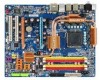
GA-EP35-DS4 Motherboard Layout RCA SPDIF-1 KB_MS SYS_FAN1 USB ATX_12V_2X LGA775 PHASE LED PWR_FAN PCIE_12V ATX 1394_2 1394_1 USB USB GA-EP35-DS4 LAN USB CPU_FAN F_AUDIO AUDIO PCIE_1 Intel® P35 RTL8111B PCIE_16_1 NB_FAN FDD DDRII1 DDRII2 DDRII3 DDRII4 CODEC PCIE_2 PCIE_3 SPDIF_O IT8718 CD_IN PCI1 PCI2 SPDIF_IN BP_BIOS MAIN_BIOS CLR_CMOS BAT PCIE_16_2 Intel® ICH9R TSB43AB23 CI SATAII4 SATAII5 SYS_FAN2 SATAII0 SATAII1 IDE SATAII2 SATAII3 GIGABYTE SATA2 GSATAII0 GSATAII1 F_USB2 F_USB1 COMA LPT F1_1394 PWR_LED F_PANEL - 7 -
GA-EP35-DS4 Motherboard Layout RCA SPDIF-1 KB_MS SYS_FAN1 USB ATX_12V_2X LGA775 PHASE LED PWR_FAN PCIE_12V ATX 1394_2 1394_1 USB USB GA-EP35-DS4 LAN USB CPU_FAN F_AUDIO AUDIO PCIE_1 Intel® P35 RTL8111B PCIE_16_1 NB_FAN FDD DDRII1 DDRII2 DDRII3 DDRII4 CODEC PCIE_2 PCIE_3 SPDIF_O IT8718 CD_IN PCI1 PCI2 SPDIF_IN BP_BIOS MAIN_BIOS CLR_CMOS BAT PCIE_16_2 Intel® ICH9R TSB43AB23 CI SATAII4 SATAII5 SYS_FAN2 SATAII0 SATAII1 IDE SATAII2 SATAII3 GIGABYTE SATA2 GSATAII0 GSATAII1 F_USB2 F_USB1 COMA LPT F1_1394 PWR_LED F_PANEL - 7 -

Manual
Page 22
... cable has been securely attached to turn off the devices and your computer. GA-EP35-DS4 Motherboard - 22 - 1-8 Internal Connectors 16 5 74 3 2 9 16 8 24 14 11 17 18 10 25 19 22 23 6 21 20 12 13 15 1) ATX_12V_2X 2) ATX 3) PCIE_12V 4) PHASE LED 5) CPU_FAN 6) SYS_FAN1/SYS_FAN2 7) PWR_FAN 8) NB_FAN 9) FDD 10) IDE 11) SATAII0/1/2/3/4/5 12) GSATAII0...
... cable has been securely attached to turn off the devices and your computer. GA-EP35-DS4 Motherboard - 22 - 1-8 Internal Connectors 16 5 74 3 2 9 16 8 24 14 11 17 18 10 25 19 22 23 6 21 20 12 13 15 1) ATX_12V_2X 2) ATX 3) PCIE_12V 4) PHASE LED 5) CPU_FAN 6) SYS_FAN1/SYS_FAN2 7) PWR_FAN 8) NB_FAN 9) FDD 10) IDE 11) SATAII0/1/2/3/4/5 12) GSATAII0...

Manual
Page 24
The higher the CPU loading, the more the number of lighted LEDs indicates the CPU loading. GA-EP35-DS4 Motherboard - 24 - 3) PCIE_12V (Power Connector) This power connector can supply extra power to an unstable system. 1 PIin No. Failure to do so may lead to the PCI Express x16 slots on the motherboard. Connect the power supply cable to this connector when using two graphics cards. Definition 1 NC 2 GND 3 GND 4 +12V 4) PHASE LED The number of lighted LEDs.
The higher the CPU loading, the more the number of lighted LEDs indicates the CPU loading. GA-EP35-DS4 Motherboard - 24 - 3) PCIE_12V (Power Connector) This power connector can supply extra power to an unstable system. 1 PIin No. Failure to do so may lead to the PCI Express x16 slots on the motherboard. Connect the power supply cable to this connector when using two graphics cards. Definition 1 NC 2 GND 3 GND 4 +12V 4) PHASE LED The number of lighted LEDs.

Manual
Page 74
...to provide exceptional power savings of up to 70% and up to run in a set period of a button. Meter Mode - GA-EP35-DS4 Motherboard - 74 - Actual performance may vary based on testing method. The Dynamic Energy Saver Interface A. Actual results may vary depending...of time. Featuring an advanced proprietary hardware and software design, GIGABYTE Dynamic Energy Saver is for reference only. Button Information Table Button Description 1 Dynamic Energy Saver On/Off Switch (Default: Off) 2 Motherboard Phase LED On/Off Switch (Default: On) 3 Dynamic CPU Frequency ...
...to provide exceptional power savings of up to 70% and up to run in a set period of a button. Meter Mode - GA-EP35-DS4 Motherboard - 74 - Actual performance may vary based on testing method. The Dynamic Energy Saver Interface A. Actual results may vary depending...of time. Featuring an advanced proprietary hardware and software design, GIGABYTE Dynamic Energy Saver is for reference only. Button Information Table Button Description 1 Dynamic Energy Saver On/Off Switch (Default: Off) 2 Motherboard Phase LED On/Off Switch (Default: On) 3 Dynamic CPU Frequency ...

Manual
Page 75
...saving reaches 99999999 Watts. - 75 - Button Information Table Button Description 1 Dynamic Energy Saver On/Off Switch (Default: Off) 2 Motherboard Phase LED On/Off Switch (Default: On) 3 Dynamic CPU Frequency Function On/Off Switch (Default: Off) 4 CPU Throttling Display 5 3-Level... CPU Voltage Switch (Default: Level 1) 6 CPU Voltage Display 7 Dynamic Power Phase Status 8 Current CPU Power Consumption 9 Time/Date Dynamic Energy Saver Enabled 10 Total Power Savings (Total power saving with Dynamic Frequency Function...
...saving reaches 99999999 Watts. - 75 - Button Information Table Button Description 1 Dynamic Energy Saver On/Off Switch (Default: Off) 2 Motherboard Phase LED On/Off Switch (Default: On) 3 Dynamic CPU Frequency Function On/Off Switch (Default: Off) 4 CPU Throttling Display 5 3-Level... CPU Voltage Switch (Default: Level 1) 6 CPU Voltage Display 7 Dynamic Power Phase Status 8 Current CPU Power Consumption 9 Time/Date Dynamic Energy Saver Enabled 10 Total Power Savings (Total power saving with Dynamic Frequency Function...


