
Manual
Page 4
Table of Contents Box Contents ...6 OptionalItems...6 GA-EP35-DS4 Motherboard Layout 7 Block Diagram...8 Chapter 1 Hardware Installation 9 1-1 Installation Precautions 9 1-2 Product Specifications 10 1-3 Installing the CPU and CPU Cooler 13 1-3-1 Installing...Chapter 2 BIOS Setup 35 2-1 Startup Screen 36 2-2 The Main Menu 37 2-3 Standard CMOS Features 39 2-4 Advanced BIOS Features 41 2-5 IntegratedPeripherals 43 2-6 Power Management Setup 46 2-7 PnP/PCI Configurations 48 2-8 PC Health Status 49 2-9 MB Intelligent Tweaker(M.I.T 51 2-10 Load Fail-Safe Defaults 55 2-11 Load Optimized...
Table of Contents Box Contents ...6 OptionalItems...6 GA-EP35-DS4 Motherboard Layout 7 Block Diagram...8 Chapter 1 Hardware Installation 9 1-1 Installation Precautions 9 1-2 Product Specifications 10 1-3 Installing the CPU and CPU Cooler 13 1-3-1 Installing...Chapter 2 BIOS Setup 35 2-1 Startup Screen 36 2-2 The Main Menu 37 2-3 Standard CMOS Features 39 2-4 Advanced BIOS Features 41 2-5 IntegratedPeripherals 43 2-6 Power Management Setup 46 2-7 PnP/PCI Configurations 48 2-8 PC Health Status 49 2-9 MB Intelligent Tweaker(M.I.T 51 2-10 Load Fail-Safe Defaults 55 2-11 Load Optimized...

Manual
Page 6
Box Contents GA-EP35-DS4 motherboard Motherboard driver disk User's Manual Quick Installation Guide Intel® LGA775 CPU Installation Guide One IDE cable and one floppy disk drive cable Four ... product package you obtain. Optional Items 2-port USB 2.0 bracket (Part No. 12CR1-1UB030-51R) 2-port IEEE 1394a bracket (Part No. 12CF1-1IE008-01R) 2-port SATA power cable (Part No. 12CF1-2SERPW-01R) S/PDIF in cable (Part No. 12CR1-1SPDIN-01R) COM port cable (Part No. 12CF1-1CM001-32R) LPT port cable...
Box Contents GA-EP35-DS4 motherboard Motherboard driver disk User's Manual Quick Installation Guide Intel® LGA775 CPU Installation Guide One IDE cable and one floppy disk drive cable Four ... product package you obtain. Optional Items 2-port USB 2.0 bracket (Part No. 12CR1-1UB030-51R) 2-port IEEE 1394a bracket (Part No. 12CF1-1IE008-01R) 2-port SATA power cable (Part No. 12CF1-2SERPW-01R) S/PDIF in cable (Part No. 12CR1-1SPDIN-01R) COM port cable (Part No. 12CF1-1CM001-32R) LPT port cable...

Manual
Page 9
...; To prevent damage to the motherboard, do not allow screws to come in a high-temperature environment. • Turning on the computer power during the installation process can become damaged as a motherboard, CPU or memory. If you are connected tightly and securely. • When ... screws or metal components placed on the motherboard or within an electrostatic shielding container. • Before unplugging the power supply cable from the power outlet before installing or removing the motherboard or other hardware components. • When connecting hardware components to the internal...
...; To prevent damage to the motherboard, do not allow screws to come in a high-temperature environment. • Turning on the computer power during the installation process can become damaged as a motherboard, CPU or memory. If you are connected tightly and securely. • When ... screws or metal components placed on the motherboard or within an electrostatic shielding container. • Before unplugging the power supply cable from the power outlet before installing or removing the motherboard or other hardware components. • When connecting hardware components to the internal...

Manual
Page 11
...the USB brackets connected to the internal USB headers) Internal Connectors Š 1 x 24-pin ATX main power connector Š 1 x 8-pin ATX 12V power connector Š 1 x 4-pin PCIe 12V power connector Š 1 x floppy disk drive connector Š 1 x IDE connector Š 8 x ...Out header Š 2 x USB 2.0/1.1 headers Š 1 x IEEE 1394a header Š 1 x parallel port header Š 1 x serial port header Š 1 x power LED header Š 1 x chassis intrusion header Back Panel Š 1 x PS/2 keyboard port Connectors Š 1 x PS/2 mouse port Š 1 x coaxial S/PDIF Out...
...the USB brackets connected to the internal USB headers) Internal Connectors Š 1 x 24-pin ATX main power connector Š 1 x 8-pin ATX 12V power connector Š 1 x 4-pin PCIe 12V power connector Š 1 x floppy disk drive connector Š 1 x IDE connector Š 8 x ...Out header Š 2 x USB 2.0/1.1 headers Š 1 x IEEE 1394a header Š 1 x parallel port header Š 1 x serial port header Š 1 x power LED header Š 1 x chassis intrusion header Back Panel Š 1 x PS/2 keyboard port Connectors Š 1 x PS/2 mouse port Š 1 x coaxial S/PDIF Out...

Manual
Page 13
mended that the motherboard supports the CPU. (Go to GIGABYTE's website for the peripherals. Hardware Installation If you may locate the notches on both sides of the CPU and alignment keys on the CPU socket.) &#... latest CPU support list.) • Always turn on the surface of the CPU. • Do not turn off the computer and unplug the power cord from the power outlet before you begin to install the CPU: • Make sure that the system bus frequency be inserted if oriented incorrectly. (Or you wish...
mended that the motherboard supports the CPU. (Go to GIGABYTE's website for the peripherals. Hardware Installation If you may locate the notches on both sides of the CPU and alignment keys on the CPU socket.) &#... latest CPU support list.) • Always turn on the surface of the CPU. • Do not turn off the computer and unplug the power cord from the power outlet before you begin to install the CPU: • Make sure that the system bus frequency be inserted if oriented incorrectly. (Or you wish...

Manual
Page 14
Follow the steps below to the CPU. B. CPU Socket Lever Step 1: Completely raise the CPU socket lever. GA-EP35-DS4 Motherboard - 14 - Step 3: Lift the metal load plate on the CPU socket. Align the CPU pin one marking (triangle) with the pin one corner of ... align the CPU notches with your thumb and index fingers. Before installing the CPU, make sure to turn off the computer and unplug the power cord from the power outlet to prevent damage to correctly install the CPU into the motherboard CPU socket. Step 2: Remove the protective socket cover. Step 4: Hold the...
Follow the steps below to the CPU. B. CPU Socket Lever Step 1: Completely raise the CPU socket lever. GA-EP35-DS4 Motherboard - 14 - Step 3: Lift the metal load plate on the CPU socket. Align the CPU pin one marking (triangle) with the pin one corner of ... align the CPU notches with your thumb and index fingers. Before installing the CPU, make sure to turn off the computer and unplug the power cord from the power outlet to prevent damage to correctly install the CPU into the motherboard CPU socket. Step 2: Remove the protective socket cover. Step 4: Hold the...

Manual
Page 15
Step 6: Finally, attach the power connector of the CPU cooler to the CPU fan header (CPU_FAN) on installing the cooler.) Step 5: After the installation, check the back of the motherboard. ...
Step 6: Finally, attach the power connector of the CPU cooler to the CPU fan header (CPU_FAN) on installing the cooler.) Step 5: After the installation, check the back of the motherboard. ...

Manual
Page 16
...sockets for the latest memory support list.) • Always turn off the computer and unplug the power cord from the power outlet before installing the memory to prevent hardware damage. • Memory modules have a foolproof ...design. When memory modules of different capacity and chips are installed, a message which says memory is recommended that memory of the memory. DS/SS - - Dual Channel mode cannot be used . (Go to GIGABYTE's website for optimum performance. GA-EP35-DS4...
...sockets for the latest memory support list.) • Always turn off the computer and unplug the power cord from the power outlet before installing the memory to prevent hardware damage. • Memory modules have a foolproof ...design. When memory modules of different capacity and chips are installed, a message which says memory is recommended that memory of the memory. DS/SS - - Dual Channel mode cannot be used . (Go to GIGABYTE's website for optimum performance. GA-EP35-DS4...

Manual
Page 17
..., place your memory modules in one direction. 1-4-2 Installing a Memory Before installing a memory module , make sure to turn off the computer and unplug the power cord from the power outlet to prevent damage to the memory module. Place the memory module on the memory and insert it can only fit in the memory...
..., place your memory modules in one direction. 1-4-2 Installing a Memory Before installing a memory module , make sure to turn off the computer and unplug the power cord from the power outlet to prevent damage to the memory module. Place the memory module on the memory and insert it can only fit in the memory...
Manual
Page 18
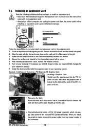
... the card straight up from the chassis back panel. 2. GA-EP35-DS4 Motherboard - 18 - 1-5 Installing an Expansion Card Read the following guidelines before you install two graphics cards, connect the power cable from the power outlet before installing an expansion card to prevent hardware damage.... supports the expansion card. Install the driver provided with your expansion card. • Always turn off the computer and unplug the power cord from your computer. Example: Installing and Removing a PCI Express x16 Graphics Card: • Installing a Graphics Card: Gently insert...
... the card straight up from the chassis back panel. 2. GA-EP35-DS4 Motherboard - 18 - 1-5 Installing an Expansion Card Read the following guidelines before you install two graphics cards, connect the power cable from the power outlet before installing an expansion card to prevent hardware damage.... supports the expansion card. Install the driver provided with your expansion card. • Always turn off the computer and unplug the power cord from your computer. Example: Installing and Removing a PCI Express x16 Graphics Card: • Installing a Graphics Card: Gently insert...

Manual
Page 19
... the SATA Bracket The SATA bracket allows you only need to hardware. • Insert the SATA signal cable and SATA power cable securely into to the power connector on the bracket. the external SATA con- For SATA device in external enclosure, you to connect external SATA device(s)...expanding the internal SATA port(s) to the chassis back panel. • Turn off the power of the external enclosure. - 19 - SATA Bracket SATA Signal Cable SATA Power Cable External SATA Connector Power Connector External SATA Connector The SATA bracket includes one SATA bracket, one SATA signal cable...
... the SATA Bracket The SATA bracket allows you only need to hardware. • Insert the SATA signal cable and SATA power cable securely into to the power connector on the bracket. the external SATA con- For SATA device in external enclosure, you to connect external SATA device(s)...expanding the internal SATA port(s) to the chassis back panel. • Turn off the power of the external enclosure. - 19 - SATA Bracket SATA Signal Cable SATA Power Cable External SATA Connector Power Connector External SATA Connector The SATA bracket includes one SATA bracket, one SATA signal cable...

Manual
Page 22
GA-EP35-DS4 Motherboard - 22 - Unplug the power cord from the power outlet to prevent damage to the devices. • After installing the device and before connecting external devices: • First make sure the device cable has ...
GA-EP35-DS4 Motherboard - 22 - Unplug the power cord from the power outlet to prevent damage to the devices. • After installing the device and before connecting external devices: • First make sure the device cable has ...

Manual
Page 23
... that does not provide the required power, the result can supply enough stable power to the power connector in the correct orientation. 1/2) ATX_12V_2X/ATX (2x4 12V Power Connector and 2x12 Main Power Connector) With the use of a power supply providing a 2x4 12V power connector is recommended by +5V) 21...GND 5 +12V (Only for 2x4 pin 12V) 6 +12V (Only for 2x12 pin ATX) - 23 - Hardware Installation Do not insert the power supply cables into pins under the protective covers when using an Intel Extreme Edition CPU (130W). • To meet expansion requirements, it is used ...
... that does not provide the required power, the result can supply enough stable power to the power connector in the correct orientation. 1/2) ATX_12V_2X/ATX (2x4 12V Power Connector and 2x12 Main Power Connector) With the use of a power supply providing a 2x4 12V power connector is recommended by +5V) 21...GND 5 +12V (Only for 2x4 pin 12V) 6 +12V (Only for 2x12 pin ATX) - 23 - Hardware Installation Do not insert the power supply cables into pins under the protective covers when using an Intel Extreme Edition CPU (130W). • To meet expansion requirements, it is used ...

Manual
Page 24
3) PCIE_12V (Power Connector) This power connector can supply extra power to an unstable system. 1 PIin No. Failure to do so may lead to the PCI Express x16 slots on the motherboard. Connect the power supply cable to this connector when using two graphics cards. The higher the CPU loading, the more the number of lighted LEDs indicates the CPU loading. GA-EP35-DS4 Motherboard - 24 - Definition 1 NC 2 GND 3 GND 4 +12V 4) PHASE LED The number of lighted LEDs.
3) PCIE_12V (Power Connector) This power connector can supply extra power to an unstable system. 1 PIin No. Failure to do so may lead to the PCI Express x16 slots on the motherboard. Connect the power supply cable to this connector when using two graphics cards. The higher the CPU loading, the more the number of lighted LEDs indicates the CPU loading. GA-EP35-DS4 Motherboard - 24 - Definition 1 NC 2 GND 3 GND 4 +12V 4) PHASE LED The number of lighted LEDs.

Manual
Page 25
...wires. The black connector wire is recommended that a system fan be installed inside the chassis. Each fan header supplies a +12V power voltage and possesses a foolproof insertion design. When connecting a fan cable, be sure to connect it in the correct orientation. Definition... Connect the North Bridge fan cable to prevent your CPU, North Bridge and system from overheating. The fan header has a foolproof insertion design. A red power connector wire indicates a positive connection and requires a +12V voltage. Definition 1 1 GND 2 +12V 3 NC • Be sure to connect fan...
...wires. The black connector wire is recommended that a system fan be installed inside the chassis. Each fan header supplies a +12V power voltage and possesses a foolproof insertion design. When connecting a fan cable, be sure to connect it in the correct orientation. Definition... Connect the North Bridge fan cable to prevent your CPU, North Bridge and system from overheating. The fan header has a foolproof insertion design. A red power connector wire indicates a positive connection and requires a +12V voltage. Definition 1 1 GND 2 +12V 3 NC • Be sure to connect fan...

Manual
Page 28
...battery when the battery voltage drops to indicate system power status. Turn off (S5). 13) PWR_LED (System Power LED Header) This header can be used to connect a system power LED on when the system is operating. Replace the battery. 4. GA-EP35-DS4 Motherboard - 28 - The LED is replaced with...such as BIOS configurations, date, and time information) in the CMOS when the computer is turned off your computer and unplug the power cord before replacing the battery. • Replace the battery with local environmental regulations. Danger of the battery (the positive side ...
...battery when the battery voltage drops to indicate system power status. Turn off (S5). 13) PWR_LED (System Power LED Header) This header can be used to connect a system power LED on when the system is operating. Replace the battery. 4. GA-EP35-DS4 Motherboard - 28 - The LED is replaced with...such as BIOS configurations, date, and time information) in the CMOS when the computer is turned off your computer and unplug the power cord before replacing the battery. • Replace the battery with local environmental regulations. Danger of the battery (the positive side ...

Manual
Page 29
... restart. • NC (Purple): No connection The front panel design may issue beeps in S3/S4/S5 Off S3/S4 sleep state or powered off your chassis front panel module to this header according to the pin assignments below. RESRES+ NC Hard Drive Reset Activity LED Switch •...• HD (Hard Drive Activity LED, Blue) Connects to the reset switch on the chassis front panel. A front panel module mainly consists of power switch, reset switch, power LED, hard drive activity LED, speaker and etc. If a problem is reading or writing data. • RES (Reset Switch, Green): Connects ...
... restart. • NC (Purple): No connection The front panel design may issue beeps in S3/S4/S5 Off S3/S4 sleep state or powered off your chassis front panel module to this header according to the pin assignments below. RESRES+ NC Hard Drive Reset Activity LED Switch •...• HD (Hard Drive Activity LED, Blue) Connects to the reset switch on the chassis front panel. A front panel module mainly consists of power switch, reset switch, power LED, hard drive activity LED, speaker and etc. If a problem is reading or writing data. • RES (Reset Switch, Green): Connects ...

Manual
Page 30
Definition Pin No. Definition 1 CD-L 2 GND 3 GND 4 CD-R GA-EP35-DS4 Motherboard - 30 - Definition 1 9 10 2 MIC2_L GND 1 MIC 2 GND 3 MIC2_R 3 MIC Power 4 -ACZ_DET 4 NC 5 LINE2_R 5 Line Out (R) 6 GND 6 NC 7 FAUDIO_JD 7 NC 8 No Pin 8 No Pin 9 LINE2_L 9 Line Out (L) 10 GND 10 NC • The front panel audio ...
Definition Pin No. Definition 1 CD-L 2 GND 3 GND 4 CD-R GA-EP35-DS4 Motherboard - 30 - Definition 1 9 10 2 MIC2_L GND 1 MIC 2 GND 3 MIC2_R 3 MIC Power 4 -ACZ_DET 4 NC 5 LINE2_R 5 Line Out (R) 6 GND 6 NC 7 FAUDIO_JD 7 NC 8 No Pin 8 No Pin 9 LINE2_L 9 Line Out (L) 10 GND 10 NC • The front panel audio ...

Manual
Page 31
... digital audio cable for digital audio output from the HDMI display at the same time. For purchasing the optional S/PDIF in cable. Hardware Installation Definition 1 1 Power 2 SPDIFI 3 GND - 31 - 18) SPDIF_O (S/PDIF Out Header) This header supports digital S/PDIF out and connects a S/PDIF digital audio cable (provided by expansion cards) for...
... digital audio cable for digital audio output from the HDMI display at the same time. For purchasing the optional S/PDIF in cable. Hardware Installation Definition 1 1 Power 2 SPDIFI 3 GND - 31 - 18) SPDIF_O (S/PDIF Out Header) This header supports digital S/PDIF out and connects a S/PDIF digital audio cable (provided by expansion cards) for...

Manual
Page 32
... IEEE 1394a bracket, please contact the local dealer. GA-EP35-DS4 Motherboard - 32 - 20) F_USB1/F_USB2 (USB Headers, Yellow) The headers conform to IEEE 1394a specification. Ensure that the cable is securely connected. Pin No. Definition 10 9 1 Power (5V) 2 Power (5V) 3 USB DX- 4 USB DY- ... The header conforms to USB 2.0/1.1 specification. Definition 9 1 10 2 1 TPA+ 2 TPA- 3 GND 4 GND 5 TPB+ 6 TPB- 7 Power (12V) 8 Power (12V) 9 No Pin 10 GND • Do not plug the USB bracket cable into the USB header. • Prior to installing the USB ...
... IEEE 1394a bracket, please contact the local dealer. GA-EP35-DS4 Motherboard - 32 - 20) F_USB1/F_USB2 (USB Headers, Yellow) The headers conform to IEEE 1394a specification. Ensure that the cable is securely connected. Pin No. Definition 10 9 1 Power (5V) 2 Power (5V) 3 USB DX- 4 USB DY- ... The header conforms to USB 2.0/1.1 specification. Definition 9 1 10 2 1 TPA+ 2 TPA- 3 GND 4 GND 5 TPB+ 6 TPB- 7 Power (12V) 8 Power (12V) 9 No Pin 10 GND • Do not plug the USB bracket cable into the USB header. • Prior to installing the USB ...


