Manual
Page 1
GA-EP35-DS3R/ GA-EP35-DS3 LGA775 socket motherboard for Intel® CoreTM processor family/ Intel® Pentium® processor family/Intel® Celeron® processor family User's Manual Rev. 2101 12ME-EP35DS3R-2101R
GA-EP35-DS3R/ GA-EP35-DS3 LGA775 socket motherboard for Intel® CoreTM processor family/ Intel® Pentium® processor family/Intel® Celeron® processor family User's Manual Rev. 2101 12ME-EP35DS3R-2101R
Manual
Page 2
Motherboard GA-EP35-DS3R/DS3 Dec. 21, 2007 Motherboard GA-EP35-DS3R/DS3 Dec. 21, 2007
Motherboard GA-EP35-DS3R/DS3 Dec. 21, 2007 Motherboard GA-EP35-DS3R/DS3 Dec. 21, 2007

Manual
Page 4
Table of Contents Box Contents ...6 OptionalItems ...6 GA-EP35-DS3R/DS3 Motherboard Layout 7 Block Diagram ...8 Chapter 1 Hardware Installation 9 1-1 Installation Precautions 9 1-2 Product Specifications 10 1-3 Installing the CPU and CPU Cooler 13 1-3-1 Installing the CPU 13 1-3-2 Installing the ...
Table of Contents Box Contents ...6 OptionalItems ...6 GA-EP35-DS3R/DS3 Motherboard Layout 7 Block Diagram ...8 Chapter 1 Hardware Installation 9 1-1 Installation Precautions 9 1-2 Product Specifications 10 1-3 Installing the CPU and CPU Cooler 13 1-3-1 Installing the CPU 13 1-3-2 Installing the ...
Manual
Page 6
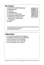
... Motherboard driver disk User's Manual Quick Installation Guide Intel® LGA775 CPU Installation Guide One IDE cable and one floppy disk drive cable GA-EP35-DS3R: Four SATA 3Gb/s cables GA-EP35-DS3: Two SATA 3Gb/s cables One SATA bracket I/O Shield • The box contents above are subject to change without notice. • The motherboard...
... Motherboard driver disk User's Manual Quick Installation Guide Intel® LGA775 CPU Installation Guide One IDE cable and one floppy disk drive cable GA-EP35-DS3R: Four SATA 3Gb/s cables GA-EP35-DS3: Two SATA 3Gb/s cables One SATA bracket I/O Shield • The box contents above are subject to change without notice. • The motherboard...
Manual
Page 7
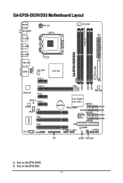
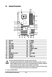
GA-EP35-DS3R/DS3 Motherboard Layout KB_MS RCA_SPDIF R_USB1 R_USB2 R_USB3 ATX_12V LGA775 PHASE LED CPU_FAN ATX GA-EP35-DS3R/DS3 DDRII1 USB_LAN F_AUDIO AUDIO SYS_FAN1 PCIE_3 PCIE_16 RTL8111B PCIE_1 SPDIF_O PCIE_2 CODEC PCI1 SPDIF_I PCI2 IT8718 CD_IN PCI3 COMA Intel® P35 FDD DDRII3 DDRII4 DDRII2 PWR_FAN BATTERY Intel® ICH9R Intel® ICH9 SATAII2 CLR_CMOS SATAII3 GSATAII0 GIGABYTE SATA2 GSATAII1 SATAII0 SATAII1 SATAII4 SATAII5 IDE1 F_USB2 F_USB1 M_BIOS CI F_PANEL LPT B_BIOS PWR_LED SYS_FAN2 Only for GA-EP35-DS3. - 7 - Only for GA-EP35-DS3R.
GA-EP35-DS3R/DS3 Motherboard Layout KB_MS RCA_SPDIF R_USB1 R_USB2 R_USB3 ATX_12V LGA775 PHASE LED CPU_FAN ATX GA-EP35-DS3R/DS3 DDRII1 USB_LAN F_AUDIO AUDIO SYS_FAN1 PCIE_3 PCIE_16 RTL8111B PCIE_1 SPDIF_O PCIE_2 CODEC PCI1 SPDIF_I PCI2 IT8718 CD_IN PCI3 COMA Intel® P35 FDD DDRII3 DDRII4 DDRII2 PWR_FAN BATTERY Intel® ICH9R Intel® ICH9 SATAII2 CLR_CMOS SATAII3 GSATAII0 GIGABYTE SATA2 GSATAII1 SATAII0 SATAII1 SATAII4 SATAII5 IDE1 F_USB2 F_USB1 M_BIOS CI F_PANEL LPT B_BIOS PWR_LED SYS_FAN2 Only for GA-EP35-DS3. - 7 - Only for GA-EP35-DS3R.
Manual
Page 8
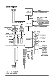
Only for GA-EP35-DS3R. Block Diagram PCIe CLK (100 MHz) LGA775 Processor CPU CLK+/(400(O.C.)/333/266/200 MHz) Host Interface DDR2 1200(O.C.)/1066/ 800/667 MHz PCI Express x16 2 SATA 3Gb/s ATA-133/100/66/33 IDE Channel GIGABYTE SATA2 LAN RJ45 RTL 8111B x1 PCI Express Bus x1 3 PCI Express x1... Speaker Out Center/Subwoofer Speaker Out Side Speaker Out MIC Line-Out Line-In SPDIF In SPDIF Out 3 PCI PCI CLK (33 MHz) Only for GA-EP35-DS3. - 8 -
Only for GA-EP35-DS3R. Block Diagram PCIe CLK (100 MHz) LGA775 Processor CPU CLK+/(400(O.C.)/333/266/200 MHz) Host Interface DDR2 1200(O.C.)/1066/ 800/667 MHz PCI Express x16 2 SATA 3Gb/s ATA-133/100/66/33 IDE Channel GIGABYTE SATA2 LAN RJ45 RTL 8111B x1 PCI Express Bus x1 3 PCI Express x1... Speaker Out Center/Subwoofer Speaker Out Side Speaker Out MIC Line-Out Line-In SPDIF In SPDIF Out 3 PCI PCI CLK (33 MHz) Only for GA-EP35-DS3. - 8 -
Manual
Page 10
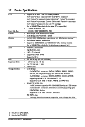
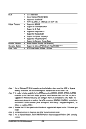
...GIGABYTE SATA2 chip: - 1 x IDE connector supporting ATA-133/100/66/33 and up to 2 IDE devices - 2 x SATA 3Gb/s connectors (GSATAII0, GSATAII1) supporting up to 1 floppy disk drive Only for SATA RAID 0, RAID 1, and JBOD Š iTE IT8718 chip: - 1 x floppy disk drive connector supporting up to 2 SATA 3Gb/s devices - GA-EP35-DS3R/DS3... 1200(O.C.)/1066/800/667 MHz memory modules (Go to GIGABYTE's website for the latest memory support list.) Š Realtek ALC889A codec Š High Definition Audio Š 2/4/5.1/7.1-channel Š Support for S/PDIF In/Out Š Support for GA-EP35-DS3.
...GIGABYTE SATA2 chip: - 1 x IDE connector supporting ATA-133/100/66/33 and up to 2 IDE devices - 2 x SATA 3Gb/s connectors (GSATAII0, GSATAII1) supporting up to 1 floppy disk drive Only for SATA RAID 0, RAID 1, and JBOD Š iTE IT8718 chip: - 1 x floppy disk drive connector supporting up to 2 SATA 3Gb/s devices - GA-EP35-DS3R/DS3... 1200(O.C.)/1066/800/667 MHz memory modules (Go to GIGABYTE's website for the latest memory support list.) Š Realtek ALC889A codec Š High Definition Audio Š 2/4/5.1/7.1-channel Š Support for S/PDIF In/Out Š Support for GA-EP35-DS3.
Manual
Page 11
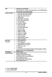
...; CPU/System/Power fan speed detection Š CPU overheating warning Š CPU/System/Power fan fail warning Š CPU fan speed control (Note 3) Only for GA-EP35-DS3. - 11 - Hardware Installation Only for...
...; CPU/System/Power fan speed detection Š CPU overheating warning Š CPU/System/Power fan fail warning Š CPU fan speed control (Note 3) Only for GA-EP35-DS3. - 11 - Hardware Installation Only for...
Manual
Page 12
The requirements above do not apply to the SATA connectors (GSATAII0, GSATAII1) controlled by the GIGABYTE SATA2 controller. (Refer to Chapter 2, "BIOS Setup," "Integrated Peripherals," for details on enabling AHCI.) (Note 3) Whether the CPU fan speed control function is supported will ... (Note 5) Š ATX Form Factor; 30.5cm x 21.0cm (Note 1) Due to chipset limitation, Intel ICH9R RAID driver does not support Windows 2000 operating system. GA-EP35-DS3R/DS3 Motherboard - 12 -
The requirements above do not apply to the SATA connectors (GSATAII0, GSATAII1) controlled by the GIGABYTE SATA2 controller. (Refer to Chapter 2, "BIOS Setup," "Integrated Peripherals," for details on enabling AHCI.) (Note 3) Whether the CPU fan speed control function is supported will ... (Note 5) Š ATX Form Factor; 30.5cm x 21.0cm (Note 1) Due to chipset limitation, Intel ICH9R RAID driver does not support Windows 2000 operating system. GA-EP35-DS3R/DS3 Motherboard - 12 -

Manual
Page 14
... off the computer and unplug the power cord from the power outlet to prevent damage to correctly install the CPU into the motherboard CPU socket. GA-EP35-DS3R/DS3 Motherboard - 14 - Step 3: Lift the metal load plate on the CPU socket. Step 4: Hold the CPU with the socket alignment keys) and gently insert...
... off the computer and unplug the power cord from the power outlet to prevent damage to correctly install the CPU into the motherboard CPU socket. GA-EP35-DS3R/DS3 Motherboard - 14 - Step 3: Lift the metal load plate on the CPU socket. Step 4: Hold the CPU with the socket alignment keys) and gently insert...
Manual
Page 16
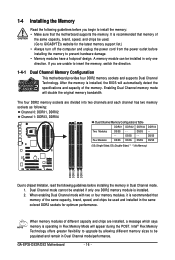
... two channels and each channel has two memory sockets as following guidelines before installing the memory to GIGABYTE's website for optimum performance. DS/SS - - Four Modules DS/SS DS/SS DS/SS DDRII4 - GA-EP35-DS3R/DS3 Motherboard - 16 - When enabling Dual Channel mode with two or four memory modules, it is operating in...
... two channels and each channel has two memory sockets as following guidelines before installing the memory to GIGABYTE's website for optimum performance. DS/SS - - Four Modules DS/SS DS/SS DS/SS DDRII4 - GA-EP35-DS3R/DS3 Motherboard - 16 - When enabling Dual Channel mode with two or four memory modules, it is operating in...
Manual
Page 18
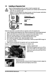
Turn on the card are completely inserted into the PCI Express x16 slot. GA-EP35-DS3R/DS3 Motherboard - 18 - If necessary, go to BIOS Setup to make any required BIOS changes for your card. Example: Installing and Removing a PCI Express x16 Graphics ...
Turn on the card are completely inserted into the PCI Express x16 slot. GA-EP35-DS3R/DS3 Motherboard - 18 - If necessary, go to BIOS Setup to make any required BIOS changes for your card. Example: Installing and Removing a PCI Express x16 Graphics ...
Manual
Page 20
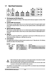
... This connector provides digital audio out to a back panel connector, first remove the cable from your audio system provides an optical digital audio in connector. GA-EP35-DS3R/DS3 Motherboard - 20 - Connection/ Speed LED Activity LED LAN Port Connection/Speed LED: State Description Orange 1 Gpbs data rate Green 100 Mpbs data rate Off...
... This connector provides digital audio out to a back panel connector, first remove the cable from your audio system provides an optical digital audio in connector. GA-EP35-DS3R/DS3 Motherboard - 20 - Connection/ Speed LED Activity LED LAN Port Connection/Speed LED: State Description Orange 1 Gpbs data rate Green 100 Mpbs data rate Off...
Manual
Page 22
... are compliant with the connectors you wish to connect. • Before installing the devices, be sure to the connector on the motherboard. Only for GA-EP35-DS3R. GA-EP35-DS3R/DS3 Motherboard - 22 - Unplug the power cord from the power outlet to prevent damage to the devices. • After installing the device and before connecting...
... are compliant with the connectors you wish to connect. • Before installing the devices, be sure to the connector on the motherboard. Only for GA-EP35-DS3R. GA-EP35-DS3R/DS3 Motherboard - 22 - Unplug the power cord from the power outlet to prevent damage to the devices. • After installing the device and before connecting...
Manual
Page 24
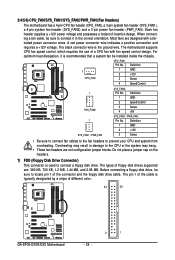
... Disk Drive Connector) This connector is the ground wire. Most fans are designed with fan speed control design. The types of different color. 34 33 GA-EP35-DS3R/DS3 Motherboard 2 1 - 24 - A red power connector wire indicates a positive connection and requires a +12V voltage. For optimum heat dissipation, it in the correct orientation. Definition 1 GND...
... Disk Drive Connector) This connector is the ground wire. Most fans are designed with fan speed control design. The types of different color. 34 33 GA-EP35-DS3R/DS3 Motherboard 2 1 - 24 - A red power connector wire indicates a positive connection and requires a +12V voltage. For optimum heat dissipation, it in the correct orientation. Definition 1 GND...
Manual
Page 26
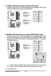
Pin No. GA-EP35-DS3R/DS3 Motherboard - 26 - If more ... L-shaped end of hard drives must be an even number. A RAID 0 or RAID 1 configuration requires at least two hard drives. The GIGABYTE SATA2 controller supports RAID 0 and RAID 1. Each SATA connector supports a single SATA device. 7 1 SATAII0 SATAII1 1 7 7 1 SATAII4 ...single SATA device. Refer to Chapter 5, "Configuring SATA Hard Drive(s)," for GA-EP35-DS3. 9) SATAII0/1/4/5 (SATA 3Gb/s Connectors, Controlled by GIGABYTE SATA2, Purple) The SATA connectors conform to SATA 3Gb/s standard and are compatible with...
Pin No. GA-EP35-DS3R/DS3 Motherboard - 26 - If more ... L-shaped end of hard drives must be an even number. A RAID 0 or RAID 1 configuration requires at least two hard drives. The GIGABYTE SATA2 controller supports RAID 0 and RAID 1. Each SATA connector supports a single SATA device. 7 1 SATAII0 SATAII1 1 7 7 1 SATAII4 ...single SATA device. Refer to Chapter 5, "Configuring SATA Hard Drive(s)," for GA-EP35-DS3. 9) SATAII0/1/4/5 (SATA 3Gb/s Connectors, Controlled by GIGABYTE SATA2, Purple) The SATA connectors conform to SATA 3Gb/s standard and are compatible with...

Manual
Page 28
..., the BIOS may configure the way to turn off (S5). • PW (Power Switch, Red): Connects to the power switch on the chassis front panel. GA-EP35-DS3R/DS3 Motherboard - 28 - The LED keeps blinking when S1 Blinking the system is in different patterns to indicate the problem. Refer to Chapter 5, "Troubleshooting," for...
..., the BIOS may configure the way to turn off (S5). • PW (Power Switch, Red): Connects to the power switch on the chassis front panel. GA-EP35-DS3R/DS3 Motherboard - 28 - The LED keeps blinking when S1 Blinking the system is in different patterns to indicate the problem. Refer to Chapter 5, "Troubleshooting," for...
Manual
Page 30
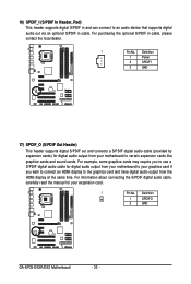
... to an audio device that supports digital audio out via an optional S/PDIF in cable, please contact the local dealer. 1 Pin No. Definition 1 SPDIFO 2 GND GA-EP35-DS3R/DS3 Motherboard - 30 - For purchasing the optional S/PDIF in cable. Definition 1 Power 2 SPDIFI 3 GND 17) SPDIF_O (S/PDIF Out Header) This header supports digital S/PDIF out...
... to an audio device that supports digital audio out via an optional S/PDIF in cable, please contact the local dealer. 1 Pin No. Definition 1 SPDIFO 2 GND GA-EP35-DS3R/DS3 Motherboard - 30 - For purchasing the optional S/PDIF in cable. Definition 1 Power 2 SPDIFI 3 GND 17) SPDIF_O (S/PDIF Out Header) This header supports digital S/PDIF out...

Manual
Page 32
... provide one parallel port via an optional LPT port cable. date information and BIOS configurations) and reset the CMOS values to clear the CMOS values (e.g. GA-EP35-DS3R/DS3 Motherboard - 32 - Open: Normal Short: Clear CMOS Values • Always turn off your computer, be sure to remove the jumper cap from the power...
... provide one parallel port via an optional LPT port cable. date information and BIOS configurations) and reset the CMOS values to clear the CMOS values (e.g. GA-EP35-DS3R/DS3 Motherboard - 32 - Open: Normal Short: Clear CMOS Values • Always turn off your computer, be sure to remove the jumper cap from the power...
Manual
Page 34
GA-EP35-DS3R/DS3 Motherboard - 34 -
GA-EP35-DS3R/DS3 Motherboard - 34 -


