User Manual
Page 2
...Features Summary 5 GA-9IVDT Motherboard Layout 7 Chapter 2 Hardware Installation Process 9 Step 1: Install the Central Processing Unit (CPU 10 Step 1-2:CPU Heat Sink Installation 11 Step 2: Install memory modules 13 Step 3: Install expansion cards 16 Step 4: Connect ribbon cables, cabinet wires, and power supply 17 Step 4-1 : I/O Back Panel Introduction 17 Step 4-2 :Connectors and Jumper Setting Introduction 19 Chapter 3 BIOS Setup 32 Main ...34 Advanced 37 PCI Configuration ...38 Advanced Chipset Control 40 Advanced Processor Option 42 Peripheral Configuration 44 Security ...48...
...Features Summary 5 GA-9IVDT Motherboard Layout 7 Chapter 2 Hardware Installation Process 9 Step 1: Install the Central Processing Unit (CPU 10 Step 1-2:CPU Heat Sink Installation 11 Step 2: Install memory modules 13 Step 3: Install expansion cards 16 Step 4: Connect ribbon cables, cabinet wires, and power supply 17 Step 4-1 : I/O Back Panel Introduction 17 Step 4-2 :Connectors and Jumper Setting Introduction 19 Chapter 3 BIOS Setup 32 Main ...34 Advanced 37 PCI Configuration ...38 Advanced Chipset Control 40 Advanced Processor Option 42 Peripheral Configuration 44 Security ...48...

User Manual
Page 3
English Table of Content Chapter 4 Technical Reference 58 Block Diagram 58 Chapter 5 Driver Installation 59 A.Intel Chipset Software Installation Utility 59 B.Broadcom BCM5705/5721 Driver Installation 61 C.Adapetc 8130 Host Raid Driver Installation 63 D.DirectX 9.0C Driver Installation 64 E.Adaptec Storage Manager Utility Installation 65 Chapter 6 Appendix 67 Acronyms ...67 3
English Table of Content Chapter 4 Technical Reference 58 Block Diagram 58 Chapter 5 Driver Installation 59 A.Intel Chipset Software Installation Utility 59 B.Broadcom BCM5705/5721 Driver Installation 61 C.Adapetc 8130 Host Raid Driver Installation 63 D.DirectX 9.0C Driver Installation 64 E.Adaptec Storage Manager Utility Installation 65 Chapter 6 Appendix 67 Acronyms ...67 3
User Manual
Page 4
... very delicate Integrated Circuit (IC) chips. Ensure that the ATX power supply is switched off , so be near the fixing hole, otherwise it may damage the board or cause board malfunctioning. 4 Installing the motherboard to SATA HDD Power cable x 2 CD for motherboard driver & utility I/O Shield x1 Serial ATA cable x 4 PATA ( 1 cables) & FDD cable set x 1 GA-9IVDT quick installation guide GA-9IVDT user's manual Retention Module x 2 WARNING! In this way you plug in or remove the ATX power connector on the base and there are...
... very delicate Integrated Circuit (IC) chips. Ensure that the ATX power supply is switched off , so be near the fixing hole, otherwise it may damage the board or cause board malfunctioning. 4 Installing the motherboard to SATA HDD Power cable x 2 CD for motherboard driver & utility I/O Shield x1 Serial ATA cable x 4 PATA ( 1 cables) & FDD cable set x 1 GA-9IVDT quick installation guide GA-9IVDT user's manual Retention Module x 2 WARNING! In this way you plug in or remove the ATX power connector on the base and there are...

User Manual
Page 5
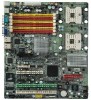
...with 360K, 720K,1.2M, 1.44M and 2.88M bytes. y GA-9IVDT Motherboard: CPU Chipset Memory I/O Control Slots On-Board IDE y Dual socket 604 for up to 2 ATAPI devices On-Board Peripherals y 1 Floppy port supports 2 FDD with HW Monitor y 2 PCI-X slot support 64/66MHz (3.3V / The Green slot supports ZCR) y 1 PCI slot supports 32/33MHz (5V) y 1 PCI-E slot by cable) y 1 x VGA port y 2 x RJ45 LAN port Hardware Monitor y CPU/Power/System Fan Revolution Detect y CPU shutdown when overtemperature y System Voltage Detect 5 Introduction Chapter 1 Introduction Features Summary Form Factor...
...with 360K, 720K,1.2M, 1.44M and 2.88M bytes. y GA-9IVDT Motherboard: CPU Chipset Memory I/O Control Slots On-Board IDE y Dual socket 604 for up to 2 ATAPI devices On-Board Peripherals y 1 Floppy port supports 2 FDD with HW Monitor y 2 PCI-X slot support 64/66MHz (3.3V / The Green slot supports ZCR) y 1 PCI slot supports 32/33MHz (5V) y 1 PCI-E slot by cable) y 1 x VGA port y 2 x RJ45 LAN port Hardware Monitor y CPU/Power/System Fan Revolution Detect y CPU shutdown when overtemperature y System Voltage Detect 5 Introduction Chapter 1 Introduction Features Summary Form Factor...

User Manual
Page 6
... update SP1 when running Windows Server 2003. English GA-9IVDTMotherboard SATA Controller On-Board SATA RAID y Adaptec® AIC-8130 chipset supports SATAII 4 ports y Supports RAID 0 ,1, 5, 10 with ZCR card (2020s) y Supports HOST RAID (RAID 0,1) y Mirroring supports automatic background rebuilds y Features LBA and Extended Interrupt 13 drive translation in controller onboard BIOS y Adaptec® AIC-8130 chipset supports SATAII interface y Build in Intel® 6300ESB chipset y RAID 0,1,5,10 are supported when ZCR card is populated. (Optional) On-Board LAN On-Board USB 2.0 PS/2 Connector...
... update SP1 when running Windows Server 2003. English GA-9IVDTMotherboard SATA Controller On-Board SATA RAID y Adaptec® AIC-8130 chipset supports SATAII 4 ports y Supports RAID 0 ,1, 5, 10 with ZCR card (2020s) y Supports HOST RAID (RAID 0,1) y Mirroring supports automatic background rebuilds y Features LBA and Extended Interrupt 13 drive translation in controller onboard BIOS y Adaptec® AIC-8130 chipset supports SATAII interface y Build in Intel® 6300ESB chipset y RAID 0,1,5,10 are supported when ZCR card is populated. (Optional) On-Board LAN On-Board USB 2.0 PS/2 Connector...
User Manual
Page 9
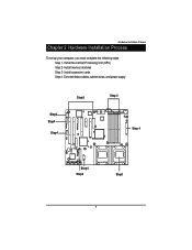
Hardware Installation Process Chapter 2 Hardware Installation Process To set up your computer, you must complete the following steps: Step 1- Install the Central Processing Unit (CPU) Step 2- Connect ribbon cables, cabinet wires, and power supply Step3 Step 2 Step4 Step4 Step4 㕺㖀㕣 㖅㖃㕲㕢 㕼㖀㖄...;㕡 㕼㕧 㕼㕡 㕼㕧 㕼㕡 㕼㕧 㕼㕡 Step4 Step4 Step1 9 Install expansion cards Step 4- Install memory modules Step 3-
Hardware Installation Process Chapter 2 Hardware Installation Process To set up your computer, you must complete the following steps: Step 1- Install the Central Processing Unit (CPU) Step 2- Connect ribbon cables, cabinet wires, and power supply Step3 Step 2 Step4 Step4 Step4 㕺㖀㕣 㖅㖃㕲㕢 㕼㖀㖄...;㕡 㕼㕧 㕼㕡 㕼㕧 㕼㕡 㕼㕧 㕼㕡 Step4 Step4 Step1 9 Install expansion cards Step 4- Install memory modules Step 3-

User Manual
Page 18
... device(s) such as USB keyboard, mouse, scanner, zip, speaker...etc. Y USB port Before you connect your device(s) into USB connector(s), please make sure your OS or device(s) vendors. LAN Port Status Description LAN Yellow LED On GIGALAN connected Green LED On GIGALAN at Speed 10/100MB Green LED Blinking Data Transfer 18 For more information please contact your OS supports USB controller. Z/[ Serial Port / VGA Port This connector supports 1 standard COM port. Device like mouse and modem etc can be connected...
... device(s) such as USB keyboard, mouse, scanner, zip, speaker...etc. Y USB port Before you connect your device(s) into USB connector(s), please make sure your OS or device(s) vendors. LAN Port Status Description LAN Yellow LED On GIGALAN connected Green LED On GIGALAN at Speed 10/100MB Green LED Blinking Data Transfer 18 For more information please contact your OS supports USB controller. Z/[ Serial Port / VGA Port This connector supports 1 standard COM port. Device like mouse and modem etc can be connected...
User Manual
Page 27
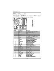
... Fan Fail LED Signal anode (+) Hard Disk LED Signal cathode(-) System Status LED Signal cathode(-) Soft Power connector anode (+) LAN1 access LED Signal Soft Power connector Ground LAN1 linked LED Signal cathode(-) Reset button cathode(-) SMBus Data Reset Button GND SMBus Clock Service ID LED Switch Case Open Signal Service ID LED Switch GND LAN2 access LED Signal NMI Switch cathode(-) LAN2 linked LED Signal cathode(-) 27 English GA-9IVDTMotherboard R ) F_Panel1 ( 2 x 12 pins connector) &Please connect the power LED, PC speaker, reset switch and power switch of your chassis front panel...
... Fan Fail LED Signal anode (+) Hard Disk LED Signal cathode(-) System Status LED Signal cathode(-) Soft Power connector anode (+) LAN1 access LED Signal Soft Power connector Ground LAN1 linked LED Signal cathode(-) Reset button cathode(-) SMBus Data Reset Button GND SMBus Clock Service ID LED Switch Case Open Signal Service ID LED Switch GND LAN2 access LED Signal NMI Switch cathode(-) LAN2 linked LED Signal cathode(-) 27 English GA-9IVDTMotherboard R ) F_Panel1 ( 2 x 12 pins connector) &Please connect the power LED, PC speaker, reset switch and power switch of your chassis front panel...

User Manual
Page 35
.../sector Japanese media format. The hard disk will not work properly if you select User Type, related information will automatically detect HDD type. Users: Set parameters by User. The 1.25MB,31/2 diskette requires 3-Mode floppy-disk drive. Auto: Set parameters automatically. (Default Vaules) CD-ROM: Use for this device. 360KB, 51/4 in. 31/2 inch AT-type high-density drive; 360K byte capacity 1.2MB, 31/2 in. 31/2 inch AT-type high-density drive; 1.2M byte capacity 720K...
.../sector Japanese media format. The hard disk will not work properly if you select User Type, related information will automatically detect HDD type. Users: Set parameters by User. The 1.25MB,31/2 diskette requires 3-Mode floppy-disk drive. Auto: Set parameters automatically. (Default Vaules) CD-ROM: Use for this device. 360KB, 51/4 in. 31/2 inch AT-type high-density drive; 360K byte capacity 1.2MB, 31/2 in. 31/2 inch AT-type high-density drive; 1.2M byte capacity 720K...
User Manual
Page 40
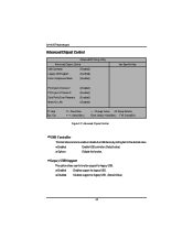
... legacy USB. Disabled Disables support for legacy USB. (Default Value) 40 Enabled Enable USB controller. (Default value) Options Disbale this function. GA-9IVDT Motherboard Advanced Chipset Control PhoenixBIOS Setup Utility Advanced Chipset Control USB Controller [Enabled] Legacy USB Support [Disabled] Force Compliance Mode [Enabled] Item Specific Help PCI-E port A Device 2 PCI-E port A1 Device 3 Data Parity Error Recovery Wake On LAN [Enabled] [Enabled] [Enabled] [Enabled] F1: Help Esc: Exit KL: Select Item IJ: Select Menu + -: Change Values F5: Setup Defaults Enter...
... legacy USB. Disabled Disables support for legacy USB. (Default Value) 40 Enabled Enable USB controller. (Default value) Options Disbale this function. GA-9IVDT Motherboard Advanced Chipset Control PhoenixBIOS Setup Utility Advanced Chipset Control USB Controller [Enabled] Legacy USB Support [Disabled] Force Compliance Mode [Enabled] Item Specific Help PCI-E port A Device 2 PCI-E port A1 Device 3 Data Parity Error Recovery Wake On LAN [Enabled] [Enabled] [Enabled] [Enabled] F1: Help Esc: Exit KL: Select Item IJ: Select Menu + -: Change Values F5: Setup Defaults Enter...
User Manual
Page 42
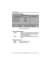
Threading technology. (Default value) Disabled Disables Hyper-Threading Technology when using Windows XP and Linux 2.4x operating systems that are optimized for Hyper- Disabled Disable this function. (Default value) 42 GA-9IVDT Motherboard Advanced Processor Option PhoenixBIOS Setup Utility Advanced Processor Option Hyper Threading Technology [Enabled] Thermal Management 2 [Disabled] Adjacent Cache Line Prefetch [Enabled] Set Max Ext CPUID = 3 [Disabled] Item Specific Help F1: Help Esc: Exit KL: Select Item IJ: Select Menu + -: Change Values F5: Setup Defaults Enter:...
Threading technology. (Default value) Disabled Disables Hyper-Threading Technology when using Windows XP and Linux 2.4x operating systems that are optimized for Hyper- Disabled Disable this function. (Default value) 42 GA-9IVDT Motherboard Advanced Processor Option PhoenixBIOS Setup Utility Advanced Processor Option Hyper Threading Technology [Enabled] Thermal Management 2 [Disabled] Adjacent Cache Line Prefetch [Enabled] Set Max Ext CPUID = 3 [Disabled] Item Specific Help F1: Help Esc: Exit KL: Select Item IJ: Select Menu + -: Change Values F5: Setup Defaults Enter:...

User Manual
Page 44
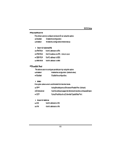
.... 3E8/IRQ4 Set IO address to 3E8. 2E8/IRQ3 Set IO address to configure serial prot A by using this option. Enabled Enable the configuration (Default value) Base I /O addreee [378] Floppy disk controller [Enabld] Floppy check [Disabld] Parallel ATA [Both] Serial ATA [Enabled] Native Mode Operation [Auto] F1: Help Esc: Exit KL: Select Item IJ: Select Menu + -: Change Values F5: Setup Defaults Enter: Select Sub-Menu F10: Save&Exit Figure 2-4: Peripheral Configuration Serial Port A This allows users to 2E8...
.... 3E8/IRQ4 Set IO address to 3E8. 2E8/IRQ3 Set IO address to configure serial prot A by using this option. Enabled Enable the configuration (Default value) Base I /O addreee [378] Floppy disk controller [Enabld] Floppy check [Disabld] Parallel ATA [Both] Serial ATA [Enabled] Native Mode Operation [Auto] F1: Help Esc: Exit KL: Select Item IJ: Select Menu + -: Change Values F5: Setup Defaults Enter: Select Sub-Menu F10: Save&Exit Figure 2-4: Peripheral Configuration Serial Port A This allows users to 2E8...
User Manual
Page 45
.... 2E8/IRQ3 Set IO address to 278. 45 EPP Using Parallel port as Extended Capabilities Port. ECP Using Parallel port as Enhanced Parallel Port. (Default) Bi-directional Use this setting to configure parallel port by using this option. Disabled Disable the configuration. Mode This option allows user to configure serial prot B by using this option. Enabled Enable the configuration (Default value) BIOS Setup Base I /O Address 378 Set IO address to 378 278 Set IO address to 2E8. Serial Port B This allows users to set Parallel Port transfer mode.
.... 2E8/IRQ3 Set IO address to 278. 45 EPP Using Parallel port as Extended Capabilities Port. ECP Using Parallel port as Enhanced Parallel Port. (Default) Bi-directional Use this setting to configure parallel port by using this option. Disabled Disable the configuration. Mode This option allows user to configure serial prot B by using this option. Enabled Enable the configuration (Default value) BIOS Setup Base I /O Address 378 Set IO address to 378 278 Set IO address to 2E8. Serial Port B This allows users to set Parallel Port transfer mode.
User Manual
Page 46
GA-9IVDT Motherboard Floppy disk controller Enabled Enable the floppy disk controller. (Default value) Disabled Disable the device. Note that certain OS is not supported under Native Mode. Select both Channel 0 and Channel 1 as Parallel ATA. (Default value) Select both Channel 1 as Parallel ATA. Native Mode Operation This option allows user to Parallel ATA. 46 Parallel ATA Set Native mode to set the native mode for ATA function. Floppy Check Enabled Disabled Enable the device to Serial ATA. Select both Channel 0 as Parallel ATA. Auto Auto detected. (Default ...
GA-9IVDT Motherboard Floppy disk controller Enabled Enable the floppy disk controller. (Default value) Disabled Disable the device. Note that certain OS is not supported under Native Mode. Select both Channel 0 and Channel 1 as Parallel ATA. (Default value) Select both Channel 1 as Parallel ATA. Native Mode Operation This option allows user to Parallel ATA. 46 Parallel ATA Set Native mode to set the native mode for ATA function. Floppy Check Enabled Disabled Enable the device to Serial ATA. Select both Channel 0 as Parallel ATA. Auto Auto detected. (Default ...
User Manual
Page 47
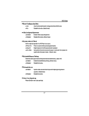
... Memory Testing. (Default value) Disabled Disable this function. Stay Off Keep the power off until the power button is removed. Network Server Enabled System will be secured at boot to prevent tampering during network operation. (Default value) Disabled Disable this function. State Set system to clear case open logs. 47 Do not power on system without pressing power button. BIOS Setup Reset Configuration Data Yes Clear the Extended System Configuration Data (ESCD) area. Pre- Clear Case Open Log Please [Enter...
... Memory Testing. (Default value) Disabled Disable this function. Stay Off Keep the power off until the power button is removed. Network Server Enabled System will be secured at boot to prevent tampering during network operation. (Default value) Disabled Disable this function. State Set system to clear case open logs. 47 Do not power on system without pressing power button. BIOS Setup Reset Configuration Data Yes Clear the Extended System Configuration Data (ESCD) area. Pre- Clear Case Open Log Please [Enter...
User Manual
Page 48
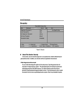
... either supervisor or user passwords, or both for different level of password securities. Type the password again and press . The password typed now will be asked to disable this option. 48 GA-9IVDT Motherboard Security Main Advanced Supervisor Password Is: User Password Is: Set Supervisor Password Set User Password Password On boot PhoenixBIOS Setup Utility Security Server Boot Clear Clear [Enter] [Enter] [Disabled] Exit Item Specific Help F1: Help Esc: Exit KL: Select Item IJ: Select Menu + -: Change Values F5: Setup Defaults Enter: Select Sub-Menu F10: Save...
... either supervisor or user passwords, or both for different level of password securities. Type the password again and press . The password typed now will be asked to disable this option. 48 GA-9IVDT Motherboard Security Main Advanced Supervisor Password Is: User Password Is: Set Supervisor Password Set User Password Password On boot PhoenixBIOS Setup Utility Security Server Boot Clear Clear [Enter] [Enter] [Disabled] Exit Item Specific Help F1: Help Esc: Exit KL: Select Item IJ: Select Menu + -: Change Values F5: Setup Defaults Enter: Select Sub-Menu F10: Save...

User Manual
Page 50
GA-9IVDT Motherboard Server PhoenixBIOS Setup Utility Main Advanced Security Server Boot Console Redirection Halt On [Mid] Memory RAS Feature Control [Standard] Clear Mem. ECC Error Info. [Disabled] Fatal Err on port A [Enabled] Exit Item Specific Help F1: Help Esc: Exit KL: Select Item IJ: Select Menu + -: Change Values F5: Setup Defaults Enter: Select Sub-Menu F10: Save&Exit Figure 4: Server Console Redirection Console Redirection Com Port Address Baud Rate Console Type Flow Control Continue...
GA-9IVDT Motherboard Server PhoenixBIOS Setup Utility Main Advanced Security Server Boot Console Redirection Halt On [Mid] Memory RAS Feature Control [Standard] Clear Mem. ECC Error Info. [Disabled] Fatal Err on port A [Enabled] Exit Item Specific Help F1: Help Esc: Exit KL: Select Item IJ: Select Menu + -: Change Values F5: Setup Defaults Enter: Select Sub-Menu F10: Save&Exit Figure 4: Server Console Redirection Console Redirection Com Port Address Baud Rate Console Type Flow Control Continue...
User Manual
Page 54
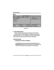
...-ROM Drive/ These three fields determines which type of device the system attempt to boot from the available devices. GA-9IVDT Motherboard Boot Main Advanced + Removable Devices CD-ROM Drive + Hard Drive PhoenixBIOS Setup Utility Security Server Boot Exit Item Specific Help F1: Help Esc: Exit KL: Select Item IJ: Select Menu + -: Change Values F5: Setup Defaults Enter: Select Sub-Menu F10: Save&Exit Figure 5: Boot * About This Section: Boot The "Boot" menu allows user to select among four possible types of boot devices listed using the key...
...-ROM Drive/ These three fields determines which type of device the system attempt to boot from the available devices. GA-9IVDT Motherboard Boot Main Advanced + Removable Devices CD-ROM Drive + Hard Drive PhoenixBIOS Setup Utility Security Server Boot Exit Item Specific Help F1: Help Esc: Exit KL: Select Item IJ: Select Menu + -: Change Values F5: Setup Defaults Enter: Select Sub-Menu F10: Save&Exit Figure 5: Boot * About This Section: Boot The "Boot" menu allows user to select among four possible types of boot devices listed using the key...
User Manual
Page 65
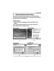
... with your motherboard into your computer. Installation Procedures: 1. Auto Run windows Install Shield Wizard 1.Click "Adaptec Storage Manager" item 2.Click "Next". (1) License Agreement (2) Install SNMP Install 3. Read through the license agreement then click "Yes". (3) 65 4.Click "Next". (4) Follow up the wizards to install the drivers. 3.Setup completed, click "Finish" to start and show the installation guide. If not, please double click the CD-ROM device icon...
... with your motherboard into your computer. Installation Procedures: 1. Auto Run windows Install Shield Wizard 1.Click "Adaptec Storage Manager" item 2.Click "Next". (1) License Agreement (2) Install SNMP Install 3. Read through the license agreement then click "Yes". (3) 65 4.Click "Next". (4) Follow up the wizards to install the drivers. 3.Setup completed, click "Finish" to start and show the installation guide. If not, please double click the CD-ROM device icon...
User Manual
Page 67
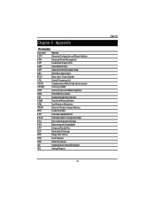
... RIMM CNR Communication and Networking Riser DMA Direct Memory Access DMI Desktop Management Interface DIMM Dual Inline Memory Module DRM Dual Retention Mechanism DRAM Dynamic Random Access Memory DDR Double Data Rate ECP Extended Capabilities Port ESCD Extended System Configuration Data ECC Error Checking and Correcting EMC Electromagnetic Compatibility EPP Enhanced Parallel Port ESD Electrostatic Discharge FDD Floppy Disk Device FSB Front Side Bus HDD Hard Disk Device IDE Integrated Dual Channel Enhanced IRQ Interrupt Request...
... RIMM CNR Communication and Networking Riser DMA Direct Memory Access DMI Desktop Management Interface DIMM Dual Inline Memory Module DRM Dual Retention Mechanism DRAM Dynamic Random Access Memory DDR Double Data Rate ECP Extended Capabilities Port ESCD Extended System Configuration Data ECC Error Checking and Correcting EMC Electromagnetic Compatibility EPP Enhanced Parallel Port ESD Electrostatic Discharge FDD Floppy Disk Device FSB Front Side Bus HDD Hard Disk Device IDE Integrated Dual Channel Enhanced IRQ Interrupt Request...


