Manual
Page 3
... in any form or by any means without prior notice. Check your motherboard looks like this manual may be reproduced, copied, translated, transmitted, or published in this product, GIGABYTE provides the following types of documentations: For quick set-up... the property of the motherboard is protected by GIGABYTE without GIGABYTE's prior written permission. For product-related information, check on our website at: http://www.gigabyte.com Identifying Your Motherboard Revision The revision number on your motherboard revision before updating motherboard BIOS, drivers, or ...
... in any form or by any means without prior notice. Check your motherboard looks like this manual may be reproduced, copied, translated, transmitted, or published in this product, GIGABYTE provides the following types of documentations: For quick set-up... the property of the motherboard is protected by GIGABYTE without GIGABYTE's prior written permission. For product-related information, check on our website at: http://www.gigabyte.com Identifying Your Motherboard Revision The revision number on your motherboard revision before updating motherboard BIOS, drivers, or ...
Manual
Page 4
Table of Contents Box Contents...6 Optional Items...6 GA-990XA-UD3 Motherboard Layout 7 GA-990XA-UD3 Motherboard Block Diagram 8 Chapter 1 Hardware Installation 9 1-1 Installation Precautions 9 1-2 Product Specifications 10 1-3 Installing the CPU and CPU Cooler 13 1-3-1 Installing the CPU 13 1-3-2 Installing the CPU Cooler ...
Table of Contents Box Contents...6 Optional Items...6 GA-990XA-UD3 Motherboard Layout 7 GA-990XA-UD3 Motherboard Block Diagram 8 Chapter 1 Hardware Installation 9 1-1 Installation Precautions 9 1-2 Product Specifications 10 1-3 Installing the CPU and CPU Cooler 13 1-3-1 Installing the CPU 13 1-3-2 Installing the CPU Cooler ...
Manual
Page 6
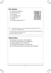
The box contents are subject to GIGABYTE's website. • The box contents above are for reference only. Optional Items 2-port USB 2.0 bracket (Part No. 12CR1-1UB030-5*R) 2-port SATA power cable (Part No. ... port cable (Part No. 12CF1-1CM001-3*R) 2-port IEEE 1394a bracket (Part No. 12CF1-1IE008-0*R) 3.5" Front Panel with 2 USB 3.0/2.0 ports (Part No. 12CR1-FPX582-0*R) - 6 - Box Contents GA-990XA-UD3 motherboard Motherboard driver disk User's Manual Quick Installation Guide Four SATA cables I/O Shield One 2-Way SLI bridge connector (Note) (Note) To enable NVIDIA SLI technology, you obtain...
The box contents are subject to GIGABYTE's website. • The box contents above are for reference only. Optional Items 2-port USB 2.0 bracket (Part No. 12CR1-1UB030-5*R) 2-port SATA power cable (Part No. ... port cable (Part No. 12CF1-1CM001-3*R) 2-port IEEE 1394a bracket (Part No. 12CF1-1IE008-0*R) 3.5" Front Panel with 2 USB 3.0/2.0 ports (Part No. 12CR1-FPX582-0*R) - 6 - Box Contents GA-990XA-UD3 motherboard Motherboard driver disk User's Manual Quick Installation Guide Four SATA cables I/O Shield One 2-Way SLI bridge connector (Note) (Note) To enable NVIDIA SLI technology, you obtain...
Manual
Page 7
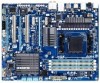
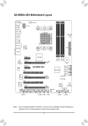
GA-990XA-UD3 Motherboard Layout KB_MS_USB OPTICAL CPU_FAN ATX_12V USB_1394 R_USB Socket AM3+ PWR_FAN R_USB30 USB_LAN Etron EJ168 ATX AUDIO PCIEX1_1(Note) AMD 990X DDR3_4 DDR3_2 DDR3_3 DDR3_1 Realtek RTL8111E CODEC PCIEX16 PCIEX1_2 PCI1 GA-990XA-UD3 VIA PCIEX8 VT6308 PCI2 iTE IT8720 PCIEX4 F_AUDIO BAT SATA3_4 SATA3_5 AMD SB950 SATA3_2 SATA3_3 SATA3_0 SATA3_1 B_BIOS M_BIOS SYS_FAN2 Etron...
GA-990XA-UD3 Motherboard Layout KB_MS_USB OPTICAL CPU_FAN ATX_12V USB_1394 R_USB Socket AM3+ PWR_FAN R_USB30 USB_LAN Etron EJ168 ATX AUDIO PCIEX1_1(Note) AMD 990X DDR3_4 DDR3_2 DDR3_3 DDR3_1 Realtek RTL8111E CODEC PCIEX16 PCIEX1_2 PCI1 GA-990XA-UD3 VIA PCIEX8 VT6308 PCI2 iTE IT8720 PCIEX4 F_AUDIO BAT SATA3_4 SATA3_5 AMD SB950 SATA3_2 SATA3_3 SATA3_0 SATA3_1 B_BIOS M_BIOS SYS_FAN2 Etron...
Manual
Page 8
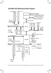
GA-990XA-UD3 Motherboard Block Diagram 2 PCI Express x8 1 PCI Express x16 CPU CLK+/- (200 MHz) AM3+/AM3 CPU DDR3 2000(O.C.)/1866/1600/1333/1066 MHz or Dual Channel ...
GA-990XA-UD3 Motherboard Block Diagram 2 PCI Express x8 1 PCI Express x16 CPU CLK+/- (200 MHz) AM3+/AM3 CPU DDR3 2000(O.C.)/1866/1600/1333/1066 MHz or Dual Channel ...

Manual
Page 9
...as physical harm to the user. • If you do not allow screws to come in a high-temperature environment. • Turning on the motherboard, make sure the power supply voltage has been set according to the local voltage standard. • Before using the product, please verify that all ...supply has been turned off. • Before turning on the power, make sure they are connected tightly and securely. • When handling the motherboard, avoid touching any installation steps or have it on top of an antistatic pad or within the computer casing. • Do not place the computer...
...as physical harm to the user. • If you do not allow screws to come in a high-temperature environment. • Turning on the motherboard, make sure the power supply voltage has been set according to the local voltage standard. • Before using the product, please verify that all ...supply has been turned off. • Before turning on the power, make sure they are connected tightly and securely. • When handling the motherboard, avoid touching any installation steps or have it on top of an antistatic pad or within the computer casing. • Do not place the computer...

Manual
Page 12
... Center ŠŠ Support for Xpress Install ŠŠ Support for Xpress Recovery2 ŠŠ Support for EasyTune * Available functions in EasyTune may differ by motherboard model. ŠŠ Support for Easy Energy Saver ŠŠ Support for Smart Recovery ŠŠ Support for Auto Green ŠŠ Support for ON...
... Center ŠŠ Support for Xpress Install ŠŠ Support for Xpress Recovery2 ŠŠ Support for EasyTune * Available functions in EasyTune may differ by motherboard model. ŠŠ Support for Easy Energy Saver ŠŠ Support for Smart Recovery ŠŠ Support for Auto Green ŠŠ Support for ON...
Manual
Page 13
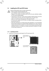
....) • Always turn on the computer if the CPU cooler is not installed, otherwise overheating and dam- It is not recommended that the motherboard supports the CPU. (Go to GIGABYTE's website for the peripherals. Locate the pin one of the CPU. If you wish to set beyond the standard specifications, please do...
....) • Always turn on the computer if the CPU cooler is not installed, otherwise overheating and dam- It is not recommended that the motherboard supports the CPU. (Go to GIGABYTE's website for the peripherals. Locate the pin one of the CPU. If you wish to set beyond the standard specifications, please do...

Manual
Page 14
... sure that the CPU pins fit perfectly into the CPU socket. Hardware Installation - 14 - B. Follow the steps below to correctly install the CPU into the motherboard CPU socket. • Before installing the CPU, make sure to turn off the computer and unplug the power cord from the power outlet to prevent...
... sure that the CPU pins fit perfectly into the CPU socket. Hardware Installation - 14 - B. Follow the steps below to correctly install the CPU into the motherboard CPU socket. • Before installing the CPU, make sure to turn off the computer and unplug the power cord from the power outlet to prevent...

Manual
Page 15
1-3-2 Installing the CPU Cooler Follow the steps below to correctly install the CPU cooler on the CPU. (The following procedure uses the GIGABYTE cooler as the picture above shows) to lock into place. (Refer to your CPU cooler installation manual for instructions on one side of the retention ... CPU. On the other side,push straight down on the the CPU cooler clip to hook it to the CPU fan header (CPU_FAN) on the motherboard. Step 2: Place the CPU cooler on the retention frame. Step 3: Hook the CPU cooler clip to the CPU. Hardware Installation Inadequately removing the CPU cooler...
1-3-2 Installing the CPU Cooler Follow the steps below to correctly install the CPU cooler on the CPU. (The following procedure uses the GIGABYTE cooler as the picture above shows) to lock into place. (Refer to your CPU cooler installation manual for instructions on one side of the retention ... CPU. On the other side,push straight down on the the CPU cooler clip to hook it to the CPU fan header (CPU_FAN) on the motherboard. Step 2: Place the CPU cooler on the retention frame. Step 3: Hook the CPU cooler clip to the CPU. Hardware Installation Inadequately removing the CPU cooler...
Manual
Page 16
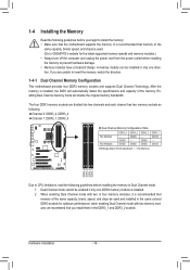
... installed, the BIOS will double the original memory bandwidth. A memory module can be used . (Go to GIGABYTE's website for optimum performance. When enabling Dual Channel mode with two memory modules, we recommend that the motherboard supports the memory. It is installed. 2. The four DDR3 memory sockets are unable to install the memory...
... installed, the BIOS will double the original memory bandwidth. A memory module can be used . (Go to GIGABYTE's website for optimum performance. When enabling Dual Channel mode with two memory modules, we recommend that the motherboard supports the memory. It is installed. 2. The four DDR3 memory sockets are unable to install the memory...

Manual
Page 17
..., make sure to turn off the computer and unplug the power cord from the power outlet to prevent damage to install DDR3 DIMMs on this motherboard. Step 1: Note the orientation of the memory, push down on the memory and insert it can only fit in the memory sockets. Spread the retaining...
..., make sure to turn off the computer and unplug the power cord from the power outlet to prevent damage to install DDR3 DIMMs on this motherboard. Step 1: Note the orientation of the memory, push down on the memory and insert it can only fit in the memory sockets. Spread the retaining...
Manual
Page 18
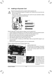
... Express x16 Slot (PCIEX16) PCI Express x16 Slot (PCIEX8/PCIEX4) PCI Slot Follow the steps below to install an expansion card: • Make sure the motherboard supports the expansion card. Locate an expansion slot that came with the slot, and press down on your expansion card(s). 7. Align the card with your...
... Express x16 Slot (PCIEX16) PCI Express x16 Slot (PCIEX8/PCIEX4) PCI Slot Follow the steps below to install an expansion card: • Make sure the motherboard supports the expansion card. Locate an expansion slot that came with the slot, and press down on your expansion card(s). 7. Align the card with your...
Manual
Page 19
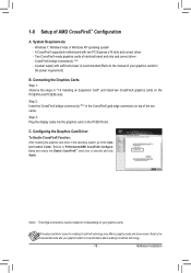
... more information about enabling CrossFireX technology. - 19 - Refer to the Catalyst Control Center. Hardware Installation Browse to the manual of the two cards. A CrossFireX-supported motherboard with sufficient power is recommended (Refer to Performance\AMD CrossFireX Configurations and ensure the Enable CrossFireX™ check box is selected and click Apply. (Note...
... more information about enabling CrossFireX technology. - 19 - Refer to the Catalyst Control Center. Hardware Installation Browse to the manual of the two cards. A CrossFireX-supported motherboard with sufficient power is recommended (Refer to Performance\AMD CrossFireX Configurations and ensure the Enable CrossFireX™ check box is selected and click Apply. (Note...

Manual
Page 21
... Audio." •• When removing the cable connected to a back panel connector, first remove the cable from your device and then remove it from the motherboard. •• When removing the cable, pull it side to side to prevent an electrical short inside the cable connector. - 21 - Microphones must be connected...
... Audio." •• When removing the cable connected to a back panel connector, first remove the cable from your device and then remove it from the motherboard. •• When removing the cable, pull it side to side to prevent an electrical short inside the cable connector. - 21 - Microphones must be connected...
Manual
Page 22
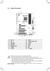
... 9) SPDIF_O 10) F_USB1/F_USB2/F_USB3 11) F_USB30 12) F_1394 13) COMA 14) TPM 15) BAT 16) CLR_CMOS Read the following guidelines before turning on the motherboard. Hardware Installation - 22 - Unplug the power cord from the power outlet to prevent damage to the devices. • After installing the device and before connecting...
... 9) SPDIF_O 10) F_USB1/F_USB2/F_USB3 11) F_USB30 12) F_1394 13) COMA 14) TPM 15) BAT 16) CLR_CMOS Read the following guidelines before turning on the motherboard. Hardware Installation - 22 - Unplug the power cord from the power outlet to prevent damage to the devices. • After installing the device and before connecting...
Manual
Page 23
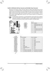
... for 2x12-pin ATX) GND (Only for 2x12-pin ATX) - 23 - To meet expansion requirements, it is turned off and all the components on the motherboard. Connect the power supply cable to the CPU. 1/2) ATX_12V/ATX (2x4 12V Power Connector and 2x12 Main Power Connector) With the use of the power...
... for 2x12-pin ATX) GND (Only for 2x12-pin ATX) - 23 - To meet expansion requirements, it is turned off and all the components on the motherboard. Connect the power supply cable to the CPU. 1/2) ATX_12V/ATX (2x4 12V Power Connector and 2x12 Main Power Connector) With the use of the power...

Manual
Page 24
... SATA device. The AMD SB950 South Bridge supports RAID 0, RAID 1, RAID 5, RAID 10, and JBOD. 3/4/5) CPU_FAN/SYS_FAN1/SYS_FAN2/PWR_FAN (Fan Headers) The motherboard has a 4-pin CPU fan header (CPU_FAN), a 4-pin (SYS_FAN1) and a 3-pin (SYS_FAN2) system fan headers, and a 3-pin power fan header ...insertion design. CPU_FAN: Pin No. Definition 1 1 GND CPU_FAN 2 +12V /Speed Control 3 Sense 4 Speed Control SYS_FAN1: Pin No. The motherboard supports CPU fan speed control, which requires the use of even number.) the SATA cable to the CPU or the system may hang. •...
... SATA device. The AMD SB950 South Bridge supports RAID 0, RAID 1, RAID 5, RAID 10, and JBOD. 3/4/5) CPU_FAN/SYS_FAN1/SYS_FAN2/PWR_FAN (Fan Headers) The motherboard has a 4-pin CPU fan header (CPU_FAN), a 4-pin (SYS_FAN1) and a 3-pin (SYS_FAN2) system fan headers, and a 3-pin power fan header ...insertion design. CPU_FAN: Pin No. Definition 1 1 GND CPU_FAN 2 +12V /Speed Control 3 Sense 4 Speed Control SYS_FAN1: Pin No. The motherboard supports CPU fan speed control, which requires the use of even number.) the SATA cable to the CPU or the system may hang. •...
Manual
Page 26
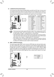
...connector match the pin assignments of a single plug. Incorrect connection between the module connector and the motherboard header will be present on each wire instead of the motherboard header. Pin No. 8) F_AUDIO (Front Panel Audio Header) The front panel audio header supports Intel...Channel Audio." For information about connecting the S/PDIF digital audio cable, carefully read the manual for digital audio output from your motherboard to this header. For example, some graphics cards may connect your chassis provides an AC'97 front panel audio module, refer...
...connector match the pin assignments of a single plug. Incorrect connection between the module connector and the motherboard header will be present on each wire instead of the motherboard header. Pin No. 8) F_AUDIO (Front Panel Audio Header) The front panel audio header supports Intel...Channel Audio." For information about connecting the S/PDIF digital audio cable, carefully read the manual for digital audio output from your motherboard to this header. For example, some graphics cards may connect your chassis provides an AC'97 front panel audio module, refer...
Manual
Page 30
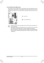
Failure to do so may cause damage to the motherboard. •• After system restart, go to BIOS Setup to load factory defaults (select Load Optimized Defaults) or manually configure the BIOS settings (refer to ...
Failure to do so may cause damage to the motherboard. •• After system restart, go to BIOS Setup to load factory defaults (select Load Optimized Defaults) or manually configure the BIOS settings (refer to ...


