Manual
Page 1
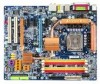
GA-965P-DS4 Intel® CoreTM 2 Extreme quad-core / CoreTM 2 Quad / Intel® CoreTM 2 Extreme dual-core / CoreTM 2 Duo / Intel® Pentium® Processor Extreme Edition / Intel® Pentium® D / Pentium® 4 LGA775 Processor Motherboard User's Manual Rev. 3301 12ME-965PDS4-3301R * The WEEE marking on the product indicates this product must not be disposed of with user's other household waste and must be handed over to a designated collection point for the recycling of waste electrical and electronic equipment!! * The WEEE marking applies only in European Union's member states.
GA-965P-DS4 Intel® CoreTM 2 Extreme quad-core / CoreTM 2 Quad / Intel® CoreTM 2 Extreme dual-core / CoreTM 2 Duo / Intel® Pentium® Processor Extreme Edition / Intel® Pentium® D / Pentium® 4 LGA775 Processor Motherboard User's Manual Rev. 3301 12ME-965PDS4-3301R * The WEEE marking on the product indicates this product must not be disposed of with user's other household waste and must be handed over to a designated collection point for the recycling of waste electrical and electronic equipment!! * The WEEE marking applies only in European Union's member states.

Manual
Page 3
... written content provided with the product. „ For detailed product information and specifications, please carefully read the "Product User Manual". „ For detailed information related to Gigabyte's unique features, please go to "Technology Guide" section on Gigabyte's website to read or download the information you need. For more product details, please click onto...
... written content provided with the product. „ For detailed product information and specifications, please carefully read the "Product User Manual". „ For detailed information related to Gigabyte's unique features, please go to "Technology Guide" section on Gigabyte's website to read or download the information you need. For more product details, please click onto...

Manual
Page 9
...below: 1. To prevent damage to the motherboard, please do not place the computer system on top of violating the conditions recommended in the provided manual. 3. Damage due to wear an electrostatic discharge (ESD) cuff when handling electronic components (CPU, RAM). 4. Please verify that all cables ... best to use of the product, please consult a certified computer technician. Damage as physical harm to be an unofficial Gigabyte product. - 9 - If you are connected. 4. Instances of electrostatic discharge (ESD). Please do not allow screws to the use of uncertified ...
...below: 1. To prevent damage to the motherboard, please do not place the computer system on top of violating the conditions recommended in the provided manual. 3. Damage due to wear an electrostatic discharge (ESD) cuff when handling electronic components (CPU, RAM). 4. Please verify that all cables ... best to use of the product, please consult a certified computer technician. Damage as physical harm to be an unofficial Gigabyte product. - 9 - If you are connected. 4. Instances of electrostatic discharge (ESD). Please do not allow screws to the use of uncertified ...

Manual
Page 14
Fig. 6 Finally, please attach the power connector of the CPU cooler to the CPU cooler installation section of the user manual) Fig. 5 Please check the back of motherboard after installing. To prevent such an occurrence, it is complete. If the push pin is inserted as a ... before installation. (This instruction is only for detailed installation instructions, please refer to the CPU fan header located on the surface of the installed CPU. GA-965P-DS4 Motherboard - 14 - Fig. 2 (Turning the push pin along the direction of arrow is to remove the CPU cooler, on the contrary, is to the ...
Fig. 6 Finally, please attach the power connector of the CPU cooler to the CPU cooler installation section of the user manual) Fig. 5 Please check the back of motherboard after installing. To prevent such an occurrence, it is complete. If the push pin is inserted as a ... before installation. (This instruction is only for detailed installation instructions, please refer to the CPU fan header located on the surface of the installed CPU. GA-965P-DS4 Motherboard - 14 - Fig. 2 (Turning the push pin along the direction of arrow is to remove the CPU cooler, on the contrary, is to the ...

Manual
Page 17
... VGA card on the card. When installing two graphics cards, please connect the power cable from its power source and read the expansion card's installation manual before installing the expansion card in the motherboard. 4. Ground yourself to prevent damage to release the card. For example: Installing a PCI Express x16 VGA card...
... VGA card on the card. When installing two graphics cards, please connect the power cable from its power source and read the expansion card's installation manual before installing the expansion card in the motherboard. 4. Ground yourself to prevent damage to release the card. For example: Installing a PCI Express x16 VGA card...

Manual
Page 34
.../SATA devices are used and the system will skip the automatic detection step and allow for faster system start up. • Manual User can use one of two methods: • Auto Allows BIOS to select this to set the access mode for faster system...Week The week, from 2000 through 2099 Time The times format in . The time is 13:00:00. Extended IDE Drive. GA-965P-DS4 Motherboard - 34 - For example, 1 p.m. You can manually input the correct settings. Access Mode Use this option for automatic device detection. Through Dec. English 2-1 Standard CMOS Features Date (...
.../SATA devices are used and the system will skip the automatic detection step and allow for faster system start up. • Manual User can use one of two methods: • Auto Allows BIOS to select this to set the access mode for faster system...Week The week, from 2000 through 2099 Time The times format in . The time is 13:00:00. Extended IDE Drive. GA-965P-DS4 Motherboard - 34 - For example, 1 p.m. You can manually input the correct settings. Access Mode Use this option for automatic device detection. Through Dec. English 2-1 Standard CMOS Features Date (...

Manual
Page 45
... Control PCI-E OverVoltage Control (G)MCH OverVoltage Control FSB OverVoltage Control CPU Voltage Control Normal CPU Vcore [Auto] [9X] [Disabled] 333 [Auto] [Disabled] [Auto] 800 [Option 1] [Manual] [Normal] [Normal] [Normal] [Normal] [Normal] 1.25000V Item Help Menu Level : Move Enter: Select F5: Previous Values +/-/PU/PD: Value F10: Save F6: Fail-Safe Defaults...
... Control PCI-E OverVoltage Control (G)MCH OverVoltage Control FSB OverVoltage Control CPU Voltage Control Normal CPU Vcore [Auto] [9X] [Disabled] 333 [Auto] [Disabled] [Auto] 800 [Option 1] [Manual] [Normal] [Normal] [Normal] [Normal] [Normal] 1.25000V Item Help Menu Level : Move Enter: Select F5: Previous Values +/-/PU/PD: Value F10: Save F6: Fail-Safe Defaults...
Manual
Page 46
... memory frequency automatically adjusted according to the CPU Host Frequency(Mhz) and System Memory Multiplier settings. (Note 2) Applies only when the GA-965P-DS4 motherboard (rev. 3.3) is highly dependent on the CPU you use a 533 MHz FSB processor, please set CPU Host Frequency to 333.... If you wish to adjust the item manually, set "System Voltage Control" to "Auto" to optimize the system voltage settings. Automatically increase CPU frequency(7%,9%) by CPU loading. Automatically increase CPU frequency(17%, 19%) by CPU loading. GA-965P-DS4 Motherboard - 46 - The actual range depends...
... memory frequency automatically adjusted according to the CPU Host Frequency(Mhz) and System Memory Multiplier settings. (Note 2) Applies only when the GA-965P-DS4 motherboard (rev. 3.3) is highly dependent on the CPU you use a 533 MHz FSB processor, please set CPU Host Frequency to 333.... If you wish to adjust the item manually, set "System Voltage Control" to "Auto" to optimize the system voltage settings. Automatically increase CPU frequency(7%,9%) by CPU loading. Automatically increase CPU frequency(17%, 19%) by CPU loading. GA-965P-DS4 Motherboard - 46 - The actual range depends...

Manual
Page 47
... ~ +0.775V Increase DDR2 voltage by 0.05V to 0.35V. Normal CPU Vcore Display your system more stable. BIOS Setup CPU Voltage Control Supports adjustable CPU vcore. Manual Manually configure the system voltage settings. (Default value) DDR2 OverVoltage Control Normal Supply DDR2 voltage as (G)MCH required. (Default value) +0.05V ~ +0.75V Increase (G)MCH voltrage by...
... ~ +0.775V Increase DDR2 voltage by 0.05V to 0.35V. Normal CPU Vcore Display your system more stable. BIOS Setup CPU Voltage Control Supports adjustable CPU vcore. Manual Manually configure the system voltage settings. (Default value) DDR2 OverVoltage Control Normal Supply DDR2 voltage as (G)MCH required. (Default value) +0.05V ~ +0.75V Increase (G)MCH voltrage by...

Manual
Page 65
... is set in your computer Attach one end of the SATA signal cable to the rear of the user's manual to identify the SATA controller for the connectors. (For example, on the GA-965P-DS4 motherboard, the SATAII0, SATAII1, SATAII2, SATAII3, SATAII4 and SATAII5 connectors are more than one hard drive. (b) An empty formatted...
... is set in your computer Attach one end of the SATA signal cable to the rear of the user's manual to identify the SATA controller for the connectors. (For example, on the GA-965P-DS4 motherboard, the SATAII0, SATAII1, SATAII2, SATAII3, SATAII4 and SATAII5 connectors are more than one hard drive. (b) An empty formatted...

Manual
Page 73
... - Appendix After pressing F6, there will load support for which you have prepared the SATA driver disk and configured BIOS settings, you are ready to manually specify an adapter. Windows Setup Setup could not determine the type of some files being loaded before you do not have chosen to install Windows...
... - Appendix After pressing F6, there will load support for which you have prepared the SATA driver disk and configured BIOS settings, you are ready to manually specify an adapter. Windows Setup Setup could not determine the type of some files being loaded before you do not have chosen to install Windows...

Manual
Page 76
...Exit F1: General Help F7: Optimized Defaults The BIOS Setup menus described in system BIOS Setup and set the first boot devce. GIGABYTE SATA2 Controller (1) Installing SATA hard drive(s) in your computer Attach one SATA controller on your motherboard, refer to the connectors introduction ...of the SATA signal cable to the rear of the user's manual to identify the SATA controller for the connectors. (For example, on the GA-965P-DS4 motherboard, the GSATAII0 and GSATAII1 connectors are supported by the GIGABYTE SATA2 controller.) Then connect the power connector from your need (Figure...
...Exit F1: General Help F7: Optimized Defaults The BIOS Setup menus described in system BIOS Setup and set the first boot devce. GIGABYTE SATA2 Controller (1) Installing SATA hard drive(s) in your computer Attach one SATA controller on your motherboard, refer to the connectors introduction ...of the SATA signal cable to the rear of the user's manual to identify the SATA controller for the connectors. (For example, on the GA-965P-DS4 motherboard, the GSATAII0 and GSATAII1 connectors are supported by the GIGABYTE SATA2 controller.) Then connect the power connector from your need (Figure...

Manual
Page 85
... party SCSI or RAID driver" message (Figure 18). Step 1: Restart your system to boot from a mass storage device manufacturer, or do not have chosen to manually specify an adapter. S=Specify Additional Device ENTER=Continue F3=Exit Figure 19 - 85 - Figure 18 Step 2: When a screen similar to install a third party SCSI or...
... party SCSI or RAID driver" message (Figure 18). Step 1: Restart your system to boot from a mass storage device manufacturer, or do not have chosen to manually specify an adapter. S=Specify Additional Device ENTER=Continue F3=Exit Figure 19 - 85 - Figure 18 Step 2: When a screen similar to install a third party SCSI or...

Manual
Page 93
... error - 93 - Answer: If your board doesn't have such jumper, you can take off power. 2. Connect power cord to MB again and turn on to GIGABYTE's website. Question 1: I still get a weak sound after updating BIOS. Press Del to the battery holder. 5. What do I cannot see these beeps usually stand for? ... the battery gently and put it aside for about 1 minute (Or you can use a metal object to connect the positive and negative pins in the manual. Appendix If your board has a Clear CMOS jumper, please refer to the steps below may help you will be able to see some boards, a...
... error - 93 - Answer: If your board doesn't have such jumper, you can take off power. 2. Connect power cord to MB again and turn on to GIGABYTE's website. Question 1: I still get a weak sound after updating BIOS. Press Del to the battery holder. 5. What do I cannot see these beeps usually stand for? ... the battery gently and put it aside for about 1 minute (Or you can use a metal object to connect the positive and negative pins in the manual. Appendix If your board has a Clear CMOS jumper, please refer to the steps below may help you will be able to see some boards, a...


