Manual
Page 1
GA-965P-DS4 Intel® CoreTM 2 Extreme quad-core / CoreTM 2 Quad / Intel® CoreTM 2 Extreme dual-core / CoreTM 2 Duo / Intel® Pentium® Processor Extreme Edition / Intel® Pentium® D / Pentium® 4 LGA775 Processor Motherboard User's Manual Rev. 3301 12ME-965PDS4-3301R * The WEEE marking on the product indicates this product must not be disposed of with user's other household waste and must be handed over to a designated collection point for the recycling of waste electrical and electronic equipment!! * The WEEE marking applies only in European Union's member states.
GA-965P-DS4 Intel® CoreTM 2 Extreme quad-core / CoreTM 2 Quad / Intel® CoreTM 2 Extreme dual-core / CoreTM 2 Duo / Intel® Pentium® Processor Extreme Edition / Intel® Pentium® D / Pentium® 4 LGA775 Processor Motherboard User's Manual Rev. 3301 12ME-965PDS4-3301R * The WEEE marking on the product indicates this product must not be disposed of with user's other household waste and must be handed over to a designated collection point for the recycling of waste electrical and electronic equipment!! * The WEEE marking applies only in European Union's member states.

Manual
Page 2
Motherboard GA-965P-DS4 Nov. 20, 2006 Motherboard GA-965P-DS4 Nov. 20, 2006
Motherboard GA-965P-DS4 Nov. 20, 2006 Motherboard GA-965P-DS4 Nov. 20, 2006

Manual
Page 4
Table of Contents ItemChecklist ...6 OptionalAccessories ...6 GA-965P-DS4 Motherboard Layout 7 Block Diagram ...8 Chapter 1 Hardware Installation 9 1-1 Considerations Prior to Installation 9 1-2 Feature Summary 10 1-3 Installation of the CPU and CPU Cooler 13 1-3-1 Installation of the ...
Table of Contents ItemChecklist ...6 OptionalAccessories ...6 GA-965P-DS4 Motherboard Layout 7 Block Diagram ...8 Chapter 1 Hardware Installation 9 1-1 Considerations Prior to Installation 9 1-2 Feature Summary 10 1-3 Installation of the CPU and CPU Cooler 13 1-3-1 Installation of the ...
Manual
Page 7
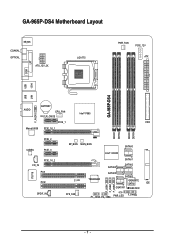
GA-965P-DS4 Motherboard Layout KB_MS COAXIAL OPTICAL ATX_12V_2X LGA775 PWR_FAN PCIE_12V ATX COM LPT 1394 USB GA-965P-DS4 LAN USB AUDIO BATTERY CPU_FAN CLR_CMOS Intel® P965 F_AUDIO PCIE_1 FDD Marvell 8056 PCIE_16_1 DDRII1 DDRII2 DDRII3 DDRII4 PCIE_2 CODEC PCIE_3 CD_IN PCIE_16_2 PCI1 IT8718 PCI2 SPDIF_IN BP_BIOS MAIN_BIOS SATAII0 CI SYS_FAN Intel® ICH8R TSB43AB23 SATAII4 SATAII1 SATAII2 SATAII5 SATAII3 GIGABYTE SATA2 IDE GSATAII1 GSATAII0 F_USB1 F_USB2 F_USB3 F1_1394 F2_1394 PWR_LED F_PANEL - 7 -
GA-965P-DS4 Motherboard Layout KB_MS COAXIAL OPTICAL ATX_12V_2X LGA775 PWR_FAN PCIE_12V ATX COM LPT 1394 USB GA-965P-DS4 LAN USB AUDIO BATTERY CPU_FAN CLR_CMOS Intel® P965 F_AUDIO PCIE_1 FDD Marvell 8056 PCIE_16_1 DDRII1 DDRII2 DDRII3 DDRII4 PCIE_2 CODEC PCIE_3 CD_IN PCIE_16_2 PCI1 IT8718 PCI2 SPDIF_IN BP_BIOS MAIN_BIOS SATAII0 CI SYS_FAN Intel® ICH8R TSB43AB23 SATAII4 SATAII1 SATAII2 SATAII5 SATAII3 GIGABYTE SATA2 IDE GSATAII1 GSATAII0 F_USB1 F_USB2 F_USB3 F1_1394 F2_1394 PWR_LED F_PANEL - 7 -
Manual
Page 8
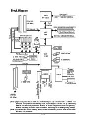
... (100 MHz) x1 x1 x1 Switch LAN RJ45 Marvell 8056 x1 PCI Express Bus 2 SATA 3Gb/s ATA-33/66/100/ 133 IDE Channel PCI Bus GIGABYTE SATA2 LGA775 Processor CPU CLK+/(333(Note 1)/266/200/133 MHz) Host Interface DDRII 800/667/533 MHz DIMM(Note 2) Intel® P965 Dual Channel.../Subwoofer Speaker Out Side Speaker Out MIC Line-Out Line-In SPDIF In SPDIF Out 2 PCI PCI CLK (33 MHz) (Note 1) Applies only when the GA-965P-DS4 motherboard (rev. 3.3) is installed. The system will be 667 MHz or 833 MHz, depending on the memory being installed. (Note 2) To use a DDRII 800/667...
... (100 MHz) x1 x1 x1 Switch LAN RJ45 Marvell 8056 x1 PCI Express Bus 2 SATA 3Gb/s ATA-33/66/100/ 133 IDE Channel PCI Bus GIGABYTE SATA2 LGA775 Processor CPU CLK+/(333(Note 1)/266/200/133 MHz) Host Interface DDRII 800/667/533 MHz DIMM(Note 2) Intel® P965 Dual Channel.../Subwoofer Speaker Out Side Speaker Out MIC Line-Out Line-In SPDIF In SPDIF Out 2 PCI PCI CLK (33 MHz) (Note 1) Applies only when the GA-965P-DS4 motherboard (rev. 3.3) is installed. The system will be 667 MHz or 833 MHz, depending on the memory being installed. (Note 2) To use a DDRII 800/667...

Manual
Page 10
... (SATAII0, SATAII1, SATAII2, SATAII3, SATAII4, SATAII5), allowing connection of 2 SATA 3Gb/s devices - Supports RAID 0, RAID 1, RAID 5, and RAID 10 for Serial ATA Š GIGABYTE SATA2 Controller - 1 IDE connectors with the PCIE_16_2 slot) (Note 3) Š 2 PCI slots GA-965P-DS4 Motherboard - 10 - TSB43AB23 chip Š 3 IEEE 1394a ports Š ICH8R Southbrigde - 1 FDD connector supported by I .
... (SATAII0, SATAII1, SATAII2, SATAII3, SATAII4, SATAII5), allowing connection of 2 SATA 3Gb/s devices - Supports RAID 0, RAID 1, RAID 5, and RAID 10 for Serial ATA Š GIGABYTE SATA2 Controller - 1 IDE connectors with the PCIE_16_2 slot) (Note 3) Š 2 PCI slots GA-965P-DS4 Motherboard - 10 - TSB43AB23 chip Š 3 IEEE 1394a ports Š ICH8R Southbrigde - 1 FDD connector supported by I .

Manual
Page 12
... on the motherboard, you must install a 1333/1066/ 800 MHz FSB processor. (Note 3) The three PCI Express x1 slots will automatically adjust BIOS to 0.775V) - GA-965P-DS4 Motherboard - 12 - The system will be unavailable when the PCIE_16_2 slot is in use. (Note 4) EasyTune functions may vary depending on different motherboards. (Note 5) The... range from 90 MHz to 0.75V) - Adjustable FSB/ DDRII frequencies Form Factor Š ATX form factor; 30.5cm x 24.4cm (Note 1) Applies only when the GA-965P-DS4 motherboard (rev. 3.3) is installed with a 1333 MHz FSB processor.
... on the motherboard, you must install a 1333/1066/ 800 MHz FSB processor. (Note 3) The three PCI Express x1 slots will automatically adjust BIOS to 0.775V) - GA-965P-DS4 Motherboard - 12 - The system will be unavailable when the PCIE_16_2 slot is in use. (Note 4) EasyTune functions may vary depending on different motherboards. (Note 5) The... range from 90 MHz to 0.75V) - Adjustable FSB/ DDRII frequencies Form Factor Š ATX form factor; 30.5cm x 24.4cm (Note 1) Applies only when the GA-965P-DS4 motherboard (rev. 3.3) is installed with a 1333 MHz FSB processor.

Manual
Page 14
... surface of the CPU cooler to the CPU fan header located on the motherboard. Fig. 6 Finally, please attach the power connector of the installed CPU. GA-965P-DS4 Motherboard - 14 - The CPU cooler may adhere to the pin hole on the motherboard.Pressing down the push pins diagonally. If the push pin is...
... surface of the CPU cooler to the CPU fan header located on the motherboard. Fig. 6 Finally, please attach the power connector of the installed CPU. GA-965P-DS4 Motherboard - 14 - The CPU cooler may adhere to the pin hole on the motherboard.Pressing down the push pins diagonally. If the push pin is...

Manual
Page 16
...want to operate the Dual Channel Technology, please note the following is configured to be enabled if only one DDRII memory module is installed. 2. The GA-965P-DS4 includes 4 DIMM sockets, and each Channel has two DIMM sockets as following: Channel 0 : DDRII1, DDRII2 Channel 1 : DDRII3, DDRII4 If you...not be populated and remain in dual-channel mode. DS/SS DS/SS DDRII3 DS/SS - English Dual Channel Memory Configuration The GA-965P-DS4 supports the Dual Channel Technology. To enable Dual Channel mode with two or four memory modules (it is recommended to the limitation of...
...want to operate the Dual Channel Technology, please note the following is configured to be enabled if only one DDRII memory module is installed. 2. The GA-965P-DS4 includes 4 DIMM sockets, and each Channel has two DIMM sockets as following: Channel 0 : DDRII1, DDRII2 Channel 1 : DDRII3, DDRII4 If you...not be populated and remain in dual-channel mode. DS/SS DS/SS DDRII3 DS/SS - English Dual Channel Memory Configuration The GA-965P-DS4 supports the Dual Channel Technology. To enable Dual Channel mode with two or four memory modules (it is recommended to the limitation of...

Manual
Page 18
... support USB controller, please contact OS vendor for possible patch or driver upgrade. If your device(s) such as USB keyboard, mouse, scanner, zip, speaker...etc. GA-965P-DS4 Motherboard - 18 - OPTICAL The SPDIF optical output port is Gigabit Ethernet , providing data transfer speeds of a printer, scanner and other peripheral devices. COM (Serial Port...
... support USB controller, please contact OS vendor for possible patch or driver upgrade. If your device(s) such as USB keyboard, mouse, scanner, zip, speaker...etc. GA-965P-DS4 Motherboard - 18 - OPTICAL The SPDIF optical output port is Gigabit Ethernet , providing data transfer speeds of a printer, scanner and other peripheral devices. COM (Serial Port...

Manual
Page 20
... are properly installed. otherwise, please do not remove it. 8 4 5 1 ATX_12V_2X Pin No. 1 2 3 4 5 6 7 8 Definition GND GND GND GND +12V +12V +12V +12V 12 24 1 13 ATX GA-965P-DS4 Motherboard Pin No. 1 2 3 4 5 6 7 8 9 10 11 12 Definition 3.3V 3.3V GND +5V GND +5V GND Power Good 5V SB(stand by processor manufacturer when using Intel...
... are properly installed. otherwise, please do not remove it. 8 4 5 1 ATX_12V_2X Pin No. 1 2 3 4 5 6 7 8 Definition GND GND GND GND +12V +12V +12V +12V 12 24 1 13 ATX GA-965P-DS4 Motherboard Pin No. 1 2 3 4 5 6 7 8 9 10 11 12 Definition 3.3V 3.3V GND +5V GND +5V GND Power Good 5V SB(stand by processor manufacturer when using Intel...

Manual
Page 22
..., and the single IDE cable can connect to one IDE device as Master and the other end of the foolproof groove in the IDE connector. 1 2 GA-965P-DS4 Motherboard 39 40 - 22 - One IDE connector can then connect to the instructions located on the IDE device). Before attaching the FDD cable, please take...
..., and the single IDE cable can connect to one IDE device as Master and the other end of the foolproof groove in the IDE connector. 1 2 GA-965P-DS4 Motherboard 39 40 - 22 - One IDE connector can then connect to the instructions located on the IDE device). Before attaching the FDD cable, please take...

Manual
Page 24
... is incorrectly replaced. Re-install the battery. 4. Plug the power cord in the battery holder to the manufacturer's instructions. Definition 1 MPD+ 1 2 MPD- 3 MPD- 12) BATTERY GA-965P-DS4 Motherboard Danger of used batteries according to make them short for about one minute. (Or you want to indicate whether the system is on the...
... is incorrectly replaced. Re-install the battery. 4. Plug the power cord in the battery holder to the manufacturer's instructions. Definition 1 MPD+ 1 2 MPD- 3 MPD- 12) BATTERY GA-965P-DS4 Motherboard Danger of used batteries according to make them short for about one minute. (Or you want to indicate whether the system is on the...

Manual
Page 26
...) Connect CD-ROM or DVD-ROM audio out to support HD Audio. If you connect the front panel audio module. Definition 1 CD-L 2 GND 3 GND 4 CD-R GA-965P-DS4 Motherboard - 26 -
...) Connect CD-ROM or DVD-ROM audio out to support HD Audio. If you connect the front panel audio module. Definition 1 CD-L 2 GND 3 GND 4 CD-R GA-965P-DS4 Motherboard - 26 -

Manual
Page 28
To clear CMOS, temporarily short the two pins. Open: Normal Short: Clear CMOS GA-965P-DS4 Motherboard - 28 - Check the pin assignment carefully while you connect the IEEE 1394 cable, incorrect connection between the cable and connector will make the device ...
To clear CMOS, temporarily short the two pins. Open: Normal Short: Clear CMOS GA-965P-DS4 Motherboard - 28 - Check the pin assignment carefully while you connect the IEEE 1394 cable, incorrect connection between the cable and connector will make the device ...

Manual
Page 30
English GA-965P-DS4 Motherboard - 30 -
English GA-965P-DS4 Motherboard - 30 -

Manual
Page 32
... Password Save & Exit Setup Exit Without Saving Dual BIOS/Q-Flash Time, Date, Hard Disk Type... 1. This action makes the system reset to access advanced options. 2. GA-965P-DS4 Motherboard - 32 - Use arrow keys to select among the items and press to select the first boot device.
... Password Save & Exit Setup Exit Without Saving Dual BIOS/Q-Flash Time, Date, Hard Disk Type... 1. This action makes the system reset to access advanced options. 2. GA-965P-DS4 Motherboard - 32 - Use arrow keys to select among the items and press to select the first boot device.

Manual
Page 34
... for faster system start up . Extended IDE Drive. is calculated base on the 24-hour military-time clock. You can manually input the correct settings. GA-965P-DS4 Motherboard - 34 - Through Dec. The time is 13:00:00. For example, 1 p.m. IDE Device Setup. Week The week, from Sun to 31 (or the maximum...
... for faster system start up . Extended IDE Drive. is calculated base on the 24-hour military-time clock. You can manually input the correct settings. GA-965P-DS4 Motherboard - 34 - Through Dec. The time is 13:00:00. For example, 1 p.m. IDE Device Setup. Week The week, from Sun to 31 (or the maximum...

Manual
Page 36
...(or add-on cards) SCSI, RAID, etc. Hard Disk Select your boot device priority by Hard Disk. LAN Select your boot device priority by LAN. GA-965P-DS4 Motherboard - 36 -
...(or add-on cards) SCSI, RAID, etc. Hard Disk Select your boot device priority by Hard Disk. LAN Select your boot device priority by LAN. GA-965P-DS4 Motherboard - 36 -

Manual
Page 38
... controller. AHCI Set the onboard SATA controller to RAID mode. USB Keyboard Support Enabled Disabled Enable USB keyboard support. Disable USB mouse support. (Default value) GA-965P-DS4 Motherboard - 38 - Disabled Set SATA Port0~3 to enable advanced Serial ATA features such as Native Command Queuing and hot plug. Advanced Host Controller Interface (AHCI...
... controller. AHCI Set the onboard SATA controller to RAID mode. USB Keyboard Support Enabled Disabled Enable USB keyboard support. Disable USB mouse support. (Default value) GA-965P-DS4 Motherboard - 38 - Disabled Set SATA Port0~3 to enable advanced Serial ATA features such as Native Command Queuing and hot plug. Advanced Host Controller Interface (AHCI...

