Manual
Page 1
GA-965P-DS4 Intel® CoreTM 2 Extreme quad-core / CoreTM 2 Quad / Intel® CoreTM 2 Extreme dual-core / CoreTM 2 Duo / Intel® Pentium® Processor Extreme Edition / Intel® Pentium® D / Pentium® 4 LGA775 Processor Motherboard User's Manual Rev. 3301 12ME-965PDS4-3301R * The WEEE marking on the product indicates this product must not be disposed of with user's other household waste and must be handed over to a designated collection point for the recycling of waste electrical and electronic equipment!! * The WEEE marking applies only in European Union's member states.
GA-965P-DS4 Intel® CoreTM 2 Extreme quad-core / CoreTM 2 Quad / Intel® CoreTM 2 Extreme dual-core / CoreTM 2 Duo / Intel® Pentium® Processor Extreme Edition / Intel® Pentium® D / Pentium® 4 LGA775 Processor Motherboard User's Manual Rev. 3301 12ME-965PDS4-3301R * The WEEE marking on the product indicates this product must not be disposed of with user's other household waste and must be handed over to a designated collection point for the recycling of waste electrical and electronic equipment!! * The WEEE marking applies only in European Union's member states.

Manual
Page 2
Motherboard GA-965P-DS4 Nov. 20, 2006 Motherboard GA-965P-DS4 Nov. 20, 2006
Motherboard GA-965P-DS4 Nov. 20, 2006 Motherboard GA-965P-DS4 Nov. 20, 2006

Manual
Page 4
Table of Contents ItemChecklist ...6 OptionalAccessories ...6 GA-965P-DS4 Motherboard Layout 7 Block Diagram ...8 Chapter 1 Hardware Installation 9 1-1 Considerations Prior to Installation 9 1-2 Feature Summary 10 1-3 Installation of the CPU and CPU Cooler 13 1-3-1 Installation of the CPU ...
Table of Contents ItemChecklist ...6 OptionalAccessories ...6 GA-965P-DS4 Motherboard Layout 7 Block Diagram ...8 Chapter 1 Hardware Installation 9 1-1 Considerations Prior to Installation 9 1-2 Feature Summary 10 1-3 Installation of the CPU and CPU Cooler 13 1-3-1 Installation of the CPU ...
Manual
Page 7
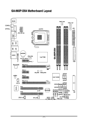
GA-965P-DS4 Motherboard Layout KB_MS COAXIAL OPTICAL ATX_12V_2X LGA775 PWR_FAN PCIE_12V ATX COM LPT 1394 USB GA-965P-DS4 LAN USB AUDIO BATTERY CPU_FAN CLR_CMOS Intel® P965 F_AUDIO PCIE_1 FDD Marvell 8056 PCIE_16_1 DDRII1 DDRII2 DDRII3 DDRII4 PCIE_2 CODEC PCIE_3 CD_IN PCIE_16_2 PCI1 IT8718 PCI2 SPDIF_IN BP_BIOS MAIN_BIOS SATAII0 CI SYS_FAN Intel® ICH8R TSB43AB23 SATAII4 SATAII1 SATAII2 SATAII5 SATAII3 GIGABYTE SATA2 IDE GSATAII1 GSATAII0 F_USB1 F_USB2 F_USB3 F1_1394 F2_1394 PWR_LED F_PANEL - 7 -
GA-965P-DS4 Motherboard Layout KB_MS COAXIAL OPTICAL ATX_12V_2X LGA775 PWR_FAN PCIE_12V ATX COM LPT 1394 USB GA-965P-DS4 LAN USB AUDIO BATTERY CPU_FAN CLR_CMOS Intel® P965 F_AUDIO PCIE_1 FDD Marvell 8056 PCIE_16_1 DDRII1 DDRII2 DDRII3 DDRII4 PCIE_2 CODEC PCIE_3 CD_IN PCIE_16_2 PCI1 IT8718 PCI2 SPDIF_IN BP_BIOS MAIN_BIOS SATAII0 CI SYS_FAN Intel® ICH8R TSB43AB23 SATAII4 SATAII1 SATAII2 SATAII5 SATAII3 GIGABYTE SATA2 IDE GSATAII1 GSATAII0 F_USB1 F_USB2 F_USB3 F1_1394 F2_1394 PWR_LED F_PANEL - 7 -
Manual
Page 8
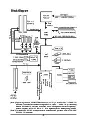
...be 667 MHz or 833 MHz, depending on the memory being installed. (Note 2) To use a DDRII 800/667 memory module on the motherboard, you must install a 1333/1066/ 800 MHz FSB processor. - 8 - PCI Express x1 PCI Express x3 Block Diagram PCIe CLK (... Switch LAN RJ45 Marvell 8056 x1 PCI Express Bus 2 SATA 3Gb/s ATA-33/66/100/ 133 IDE Channel PCI Bus GIGABYTE SATA2 LGA775 Processor CPU CLK+/(333(Note 1)/266/200/133 MHz) Host Interface DDRII 800/667/533 MHz DIMM(Note 2) ... SPDIF In SPDIF Out 2 PCI PCI CLK (33 MHz) (Note 1) Applies only when the GA-965P-DS4 motherboard (rev. 3.3) is installed.
...be 667 MHz or 833 MHz, depending on the memory being installed. (Note 2) To use a DDRII 800/667 memory module on the motherboard, you must install a 1333/1066/ 800 MHz FSB processor. - 8 - PCI Express x1 PCI Express x3 Block Diagram PCIe CLK (... Switch LAN RJ45 Marvell 8056 x1 PCI Express Bus 2 SATA 3Gb/s ATA-33/66/100/ 133 IDE Channel PCI Bus GIGABYTE SATA2 LGA775 Processor CPU CLK+/(333(Note 1)/266/200/133 MHz) Host Interface DDRII 800/667/533 MHz DIMM(Note 2) ... SPDIF In SPDIF Out 2 PCI PCI CLK (33 MHz) (Note 1) Applies only when the GA-965P-DS4 motherboard (rev. 3.3) is installed.

Manual
Page 9
...is switched off the computer and unplug its components. 5. Prior to improper installation. 4. Please do not place the computer system on the motherboard or within a electrostatic shielding container. 5. If you are connected. 4. Damage as a result of violating the conditions recommended in the ...related to the use of Non-Warranty 1. Before using the product, please verify that the power supply is best to be an unofficial Gigabyte product. - 9 - Damage due to use of the product, please consult a certified computer technician. Instances of uncertified components. 5. ...
...is switched off the computer and unplug its components. 5. Prior to improper installation. 4. Please do not place the computer system on the motherboard or within a electrostatic shielding container. 5. If you are connected. 4. Damage as a result of violating the conditions recommended in the ...related to the use of Non-Warranty 1. Before using the product, please verify that the power supply is best to be an unofficial Gigabyte product. - 9 - Damage due to use of the product, please consult a certified computer technician. Instances of uncertified components. 5. ...

Manual
Page 10
Supports RAID 0, RAID 1, RAID 5, and RAID 10 for Serial ATA Š GIGABYTE SATA2 Controller - 1 IDE connectors with CPU Š Supports 1333(Note 1)/1066/800/533 MHz FSB Š Northbridge: Intel® P965 Express Chipset Š Southbridge: Intel&#...; 1 PCI Express x4 slot (the PCIE_16_2 slot) Š 3 PCI Express x1 slots (share the same PCIe bus with the PCIE_16_2 slot) (Note 3) Š 2 PCI slots GA-965P-DS4 Motherboard - 10 - TSB43AB23 chip Š 3 IEEE 1394a ports Š ICH8R Southbrigde - 1 FDD connector supported by I .
Supports RAID 0, RAID 1, RAID 5, and RAID 10 for Serial ATA Š GIGABYTE SATA2 Controller - 1 IDE connectors with CPU Š Supports 1333(Note 1)/1066/800/533 MHz FSB Š Northbridge: Intel® P965 Express Chipset Š Southbridge: Intel&#...; 1 PCI Express x4 slot (the PCIE_16_2 slot) Š 3 PCI Express x1 slots (share the same PCIe bus with the PCIE_16_2 slot) (Note 3) Š 2 PCI slots GA-965P-DS4 Motherboard - 10 - TSB43AB23 chip Š 3 IEEE 1394a ports Š ICH8R Southbrigde - 1 FDD connector supported by I .

Manual
Page 12
Adjustable FSB/ DDRII frequencies Form Factor Š ATX form factor; 30.5cm x 24.4cm (Note 1) Applies only when the GA-965P-DS4 motherboard (rev. 3.3) is installed. DIMM Over Voltage : Adjustable DIMM voltage at 0.025V (Note 5) - The system will be 667 MHz or 833 MHz, depending on the memory... Voltage : Adjustable (G)MCH(Northbridge) voltage at 0.05V (Adjustable range from 90 MHz to 0.35V) Š Over Clock via BIOS (CPU/ DDRII/ PCI-E/ (G)MCH/ FSB) - GA-965P-DS4 Motherboard - 12 - PCI Express x16 Frequency : Allows 1 MHz increment from 0.05V to 150 MHz -
Adjustable FSB/ DDRII frequencies Form Factor Š ATX form factor; 30.5cm x 24.4cm (Note 1) Applies only when the GA-965P-DS4 motherboard (rev. 3.3) is installed. DIMM Over Voltage : Adjustable DIMM voltage at 0.025V (Note 5) - The system will be 667 MHz or 833 MHz, depending on the memory... Voltage : Adjustable (G)MCH(Northbridge) voltage at 0.05V (Adjustable range from 90 MHz to 0.35V) Š Over Clock via BIOS (CPU/ DDRII/ PCI-E/ (G)MCH/ FSB) - GA-965P-DS4 Motherboard - 12 - PCI Express x16 Frequency : Allows 1 MHz increment from 0.05V to 150 MHz -

Manual
Page 13
... make sure that has optimizations for the peripherals. If you install the CPU in accordance with the processor specifications. OS: An operation system that the motherboard supports the CPU. 2. If you wish to set the frequency beyond hardware specifications since it does not meet the required standards for HT Technology 1-3-1 Installation...
... make sure that has optimizations for the peripherals. If you install the CPU in accordance with the processor specifications. OS: An operation system that the motherboard supports the CPU. 2. If you wish to set the frequency beyond hardware specifications since it does not meet the required standards for HT Technology 1-3-1 Installation...

Manual
Page 14
... of the CPU cooler to the CPU fan header located on the motherboard. To prevent such an occurrence, it is inserted as a result of hardening of motherboard after installing. Fig. 6 Finally, please attach the power connector of the installed CPU. GA-965P-DS4 Motherboard - 14 - Fig. 4 Please make sure the push pins aim to the pin...
... of the CPU cooler to the CPU fan header located on the motherboard. To prevent such an occurrence, it is inserted as a result of hardening of motherboard after installing. Fig. 6 Finally, please attach the power connector of the installed CPU. GA-965P-DS4 Motherboard - 14 - Fig. 4 Please make sure the push pins aim to the pin...

Manual
Page 15
... DIMM memory module vertically into the DIMM socket. The memory capacity used is switched off to lock the DIMM module. The motherboard supports DDRII memory modules, whereby BIOS will automatically detect memory capacity and specifications. Reverse the installation steps when you are designed ...so that the computer power is supported by the motherboard. Memory modules are unable to remove the DIMM module. - 15 - Please make sure that they can be inserted only in...
... DIMM memory module vertically into the DIMM socket. The memory capacity used is switched off to lock the DIMM module. The motherboard supports DDRII memory modules, whereby BIOS will automatically detect memory capacity and specifications. Reverse the installation steps when you are designed ...so that the computer power is supported by the motherboard. Memory modules are unable to remove the DIMM module. - 15 - Please make sure that they can be inserted only in...

Manual
Page 16
The GA-965P-DS4 includes 4 DIMM sockets, and each Channel has two DIMM sockets as following: Channel 0 : DDRII1, DDRII2 Channel 1 : DDRII3, DDRII4 If you must install them into DIMM ... use memory modules of memory bus will not be populated and remain in dual-channel mode. DS/SS DDRII2 - English Dual Channel Memory Configuration The GA-965P-DS4 supports the Dual Channel Technology. GA-965P-DS4 Motherboard - 16 -
The GA-965P-DS4 includes 4 DIMM sockets, and each Channel has two DIMM sockets as following: Channel 0 : DDRII1, DDRII2 Channel 1 : DDRII3, DDRII4 If you must install them into DIMM ... use memory modules of memory bus will not be populated and remain in dual-channel mode. DS/SS DDRII2 - English Dual Channel Memory Configuration The GA-965P-DS4 supports the Dual Channel Technology. GA-965P-DS4 Motherboard - 16 -

Manual
Page 17
...resulting from the PCIE_16_2 slot: When you try to release the card. To remove the VGA card from Electrostatic discharge (ESD). 3. The motherboard includes a PCIE_12V power connector, which provides extra power to secure the slot bracket of the PCIE_16 slot when you try to uninstall the VGA... 5. Power on the opposite side of Expansion Cards To install your expansion card, follow the steps below. 1. Install related driver in the motherboard. 4. Make sure the VGA card is locked by the small white drawable bar. Disconnect your computer's chassis cover, screws and slot bracket ...
...resulting from the PCIE_16_2 slot: When you try to release the card. To remove the VGA card from Electrostatic discharge (ESD). 3. The motherboard includes a PCIE_12V power connector, which provides extra power to secure the slot bracket of the PCIE_16 slot when you try to uninstall the VGA... 5. Power on the opposite side of Expansion Cards To install your expansion card, follow the steps below. 1. Install related driver in the motherboard. 4. Make sure the VGA card is locked by the small white drawable bar. Disconnect your computer's chassis cover, screws and slot bracket ...

Manual
Page 18
.../100/ 1000 Mbps. IEEE 1394a Port Serial interface standard set by Institute of a printer, scanner and other peripheral devices. If your OS supports USB controller. GA-965P-DS4 Motherboard - 18 - Center/Subwoofer speakers can be connected to an external Dolby Digital Decoder via a coaxial cable. Parallel Port The parallel port allows connection of Electrical...
.../100/ 1000 Mbps. IEEE 1394a Port Serial interface standard set by Institute of a printer, scanner and other peripheral devices. If your OS supports USB controller. GA-965P-DS4 Motherboard - 18 - Center/Subwoofer speakers can be connected to an external Dolby Digital Decoder via a coaxial cable. Parallel Port The parallel port allows connection of Electrical...

Manual
Page 20
... provides a 24-pin ATX or 2x4 pin ATX 12V power connector, please remove the small cover on the power connector on the motherboard and connect tightly. Before connecting the power connector, please make sure that can withstand high power consumption be used that does not provide... do not remove it. 8 4 5 1 ATX_12V_2X Pin No. 1 2 3 4 5 6 7 8 Definition GND GND GND GND +12V +12V +12V +12V 12 24 1 13 ATX GA-965P-DS4 Motherboard Pin No. 1 2 3 4 5 6 7 8 9 10 11 12 Definition 3.3V 3.3V GND +5V GND +5V GND Power Good 5V SB(stand by processor manufacturer when using Intel®...
... provides a 24-pin ATX or 2x4 pin ATX 12V power connector, please remove the small cover on the power connector on the motherboard and connect tightly. Before connecting the power connector, please make sure that can withstand high power consumption be used that does not provide... do not remove it. 8 4 5 1 ATX_12V_2X Pin No. 1 2 3 4 5 6 7 8 Definition GND GND GND GND +12V +12V +12V +12V 12 24 1 13 ATX GA-965P-DS4 Motherboard Pin No. 1 2 3 4 5 6 7 8 9 10 11 12 Definition 3.3V 3.3V GND +5V GND +5V GND Power Good 5V SB(stand by processor manufacturer when using Intel®...

Manual
Page 22
Before attaching the FDD cable, please take note of the foolproof groove in the IDE connector. 1 2 GA-965P-DS4 Motherboard 39 40 - 22 - One IDE connector can connect to one IDE device as Master and the other end of FDD drives supported are: 360 KB, ...
Before attaching the FDD cable, please take note of the foolproof groove in the IDE connector. 1 2 GA-965P-DS4 Motherboard 39 40 - 22 - One IDE connector can connect to one IDE device as Master and the other end of FDD drives supported are: 360 KB, ...

Manual
Page 24
... holder to indicate whether the system is incorrectly replaced. Dispose of explosion if battery is on the computer. - 24 - Definition 1 MPD+ 1 2 MPD- 3 MPD- 12) BATTERY GA-965P-DS4 Motherboard Danger of used batteries according to erase CMOS... 1. It will blink when the system enters suspend mode(S1).
... holder to indicate whether the system is incorrectly replaced. Dispose of explosion if battery is on the computer. - 24 - Definition 1 MPD+ 1 2 MPD- 3 MPD- 12) BATTERY GA-965P-DS4 Motherboard Danger of used batteries according to erase CMOS... 1. It will blink when the system enters suspend mode(S1).

Manual
Page 26
... 7 NC 8 No Pin 9 Line Out (L) 10 NC By default, the audio driver is configured to work or even damage it. Definition 1 CD-L 2 GND 3 GND 4 CD-R GA-965P-DS4 Motherboard - 26 - English 14) F_AUDIO (Front Audio Connector) This connector supports either HD (High Definition) or AC97 front panel audio module. Check the pin assignments carefully...
... 7 NC 8 No Pin 9 Line Out (L) 10 NC By default, the audio driver is configured to work or even damage it. Definition 1 CD-L 2 GND 3 GND 4 CD-R GA-965P-DS4 Motherboard - 26 - English 14) F_AUDIO (Front Audio Connector) This connector supports either HD (High Definition) or AC97 front panel audio module. Check the pin assignments carefully...

Manual
Page 28
... speed, high bandwidth and hot plug. Default doesn't include the jumper to avoid improper use of this header. Pin No. Open: Normal Short: Clear CMOS GA-965P-DS4 Motherboard - 28 - Check the pin assignment carefully while you connect the IEEE 1394 cable, incorrect connection between the cable and connector will make the device unable...
... speed, high bandwidth and hot plug. Default doesn't include the jumper to avoid improper use of this header. Pin No. Open: Normal Short: Clear CMOS GA-965P-DS4 Motherboard - 28 - Check the pin assignment carefully while you connect the IEEE 1394 cable, incorrect connection between the cable and connector will make the device unable...

Manual
Page 30
English GA-965P-DS4 Motherboard - 30 -
English GA-965P-DS4 Motherboard - 30 -


