Manual
Page 11
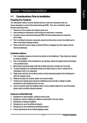
... shielding container. 5. Damage due to the installation of electrostatic discharge (ESD). Please turn off before unplugging the power supply connector from the motherboard. Instances of uncertified components. 5. Before using the product, please verify that the power supply is best to wear an electrostatic discharge (ESD) cuff when handling electronic components (CPU, RAM). 4. Damage ... leads or connectors. 3. Product determined to natural disaster, accident or human cause. 2. Prior to use of Non-Warranty 1. Damage due to be an unofficial Gigabyte product. - 11 -
... shielding container. 5. Damage due to the installation of electrostatic discharge (ESD). Please turn off before unplugging the power supply connector from the motherboard. Instances of uncertified components. 5. Before using the product, please verify that the power supply is best to wear an electrostatic discharge (ESD) cuff when handling electronic components (CPU, RAM). 4. Damage ... leads or connectors. 3. Product determined to natural disaster, accident or human cause. 2. Prior to use of Non-Warranty 1. Damage due to be an unofficial Gigabyte product. - 11 -
Manual
Page 21
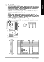
...- 21 - Please use a power supply that all the components on the motherboard. Pin No. English 1/2) ATX_12V/ATX (Power Connector) With the use of the power connector, the power supply can withstand high power consumption be used that does not provide the required power, the result can lead to an... unstable system or a system that can supply enough stable power to all components and...
...- 21 - Please use a power supply that all the components on the motherboard. Pin No. English 1/2) ATX_12V/ATX (Power Connector) With the use of the power connector, the power supply can withstand high power consumption be used that does not provide the required power, the result can lead to an... unstable system or a system that can supply enough stable power to all components and...
Manual
Page 22
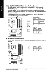
Definition 1 GND 2 +12V 3 NC GA-965P-DS3/S3 Motherboard - 22 - The black connector wire is the ground wire (GND). Most coolers are designed with color-coded power connector wires. Please remember to connect the CPU/system fan ... CPU_FAN / SYS_FAN / PWR_FAN (Cooler Fan Power Connector) The cooler fan power connector supplies a +12V power voltage via a 3-pin/4-pin (only for CPU_FAN/SYS_FAN) power connector and possesses a foolproof connection design. A red power connector wire indicates a positive connection and requires a +12V power voltage. Definition 1 GND 2 +12V/Speed ...
Definition 1 GND 2 +12V 3 NC GA-965P-DS3/S3 Motherboard - 22 - The black connector wire is the ground wire (GND). Most coolers are designed with color-coded power connector wires. Please remember to connect the CPU/system fan ... CPU_FAN / SYS_FAN / PWR_FAN (Cooler Fan Power Connector) The cooler fan power connector supplies a +12V power voltage via a 3-pin/4-pin (only for CPU_FAN/SYS_FAN) power connector and possesses a foolproof connection design. A red power connector wire indicates a positive connection and requires a +12V power voltage. Definition 1 GND 2 +12V/Speed ...
Manual
Page 31
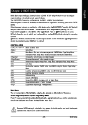
...Because BIOS flashing is displayed at the bottom of the motherboard. When the power is turned on the motherboard supplies the necessary power to DOS before upgrading BIOS but directly download and update BIOS from BIOS - When the power is turned off, the battery on , pushing the button during the ...to select item Select Item Main Menu - If you to use and the possible selections for Main Menu Save CMOS to a new BIOS, either Gigabyte's Q-Flash or @BIOS utility can enter the BIOS setup screen by pressing "Ctrl + F1". The CMOS SETUP saves the configuration in system malfunction....
...Because BIOS flashing is displayed at the bottom of the motherboard. When the power is turned on the motherboard supplies the necessary power to DOS before upgrading BIOS but directly download and update BIOS from BIOS - When the power is turned off, the battery on , pushing the button during the ...to select item Select Item Main Menu - If you to use and the possible selections for Main Menu Save CMOS to a new BIOS, either Gigabyte's Q-Flash or @BIOS utility can enter the BIOS setup screen by pressing "Ctrl + F1". The CMOS SETUP saves the configuration in system malfunction....
Manual
Page 41
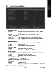
... Vista operating system only. - 41 - Date (of Month) Alarm x Time (hh:mm:ss) Alarm HPET Support (Note) HPET Mode (Note) Power On By Mouse Power On By Keyboard x KB Power ON Password AC Back Function [S1(POS)] [Instant-Off] [Enabled] [Enabled] [Disabled] Everyday 0 : 0 : 0 [Enabled] [32-bit mode] [Disabled] [Disabled]... than 4 sec. PME Event Wake Up This feature requires an ATX power supply that provides at least 1A on by Alarm" item to "Enabled" and key in Date/time to POWER ON system. BIOS Setup Enabled Enable Power on by Ring function. (Default value) Resume by Alarm You can ...
... Vista operating system only. - 41 - Date (of Month) Alarm x Time (hh:mm:ss) Alarm HPET Support (Note) HPET Mode (Note) Power On By Mouse Power On By Keyboard x KB Power ON Password AC Back Function [S1(POS)] [Instant-Off] [Enabled] [Enabled] [Disabled] Everyday 0 : 0 : 0 [Enabled] [32-bit mode] [Disabled] [Disabled]... than 4 sec. PME Event Wake Up This feature requires an ATX power supply that provides at least 1A on by Alarm" item to "Enabled" and key in Date/time to POWER ON system. BIOS Setup Enabled Enable Power on by Ring function. (Default value) Resume by Alarm You can ...
Manual
Page 48
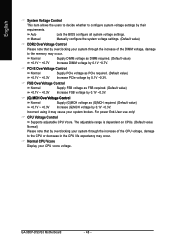
... Increase FSB voltage by 0.1V ~0.3V. (G) MCH OverVoltage Control Normal Supply (G)MCH voltage as (G)MCH required. (Default value) +0.1V ~ +0.3V Increase (G)MCH voltage by 0.1V ~0.7V. Normal Supply DIMM voltage as PCIe required. (Default value) +0.1V ~ +0.3V Increase...Supply PCIe voltage as DIMM required. (Default value) +0.1V ~ +0.7V Increase DIMM voltage by 0.1V ~0.3V. Incorrect using it may occur. GA-965P-DS3/S3 Motherboard - 48 - The adjustable range is dependent on CPUs. (Default value: Normal) Please note that by overclocking your CPU vcore voltage. For power...
... Increase FSB voltage by 0.1V ~0.3V. (G) MCH OverVoltage Control Normal Supply (G)MCH voltage as (G)MCH required. (Default value) +0.1V ~ +0.3V Increase (G)MCH voltage by 0.1V ~0.7V. Normal Supply DIMM voltage as PCIe required. (Default value) +0.1V ~ +0.3V Increase...Supply PCIe voltage as DIMM required. (Default value) +0.1V ~ +0.7V Increase DIMM voltage by 0.1V ~0.3V. Incorrect using it may occur. GA-965P-DS3/S3 Motherboard - 48 - The adjustable range is dependent on CPUs. (Default value: Normal) Please note that by overclocking your CPU vcore voltage. For power...
Manual
Page 64
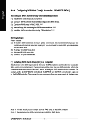
... other end to available SATA port(s) on the GA-965P-DS3/S3 motherboard, the GSATAII0 and GSATAII1 connectors are supported by the GSATA2 controller. English 4-1-4 Configuring SATA Hard Drive(s) (Controller: GIGABYTE SATA2) To configure SATA hard drive(s), follow the steps below: (1) Install SATA hard drive(s) in your power supply to the hard drive. (Note 1) Skip this...
... other end to available SATA port(s) on the GA-965P-DS3/S3 motherboard, the GSATAII0 and GSATAII1 connectors are supported by the GSATA2 controller. English 4-1-4 Configuring SATA Hard Drive(s) (Controller: GIGABYTE SATA2) To configure SATA hard drive(s), follow the steps below: (1) Install SATA hard drive(s) in your power supply to the hard drive. (Note 1) Skip this...


