Manual
Page 1
GA-965P-DQ6 Intel® CoreTM 2 Extreme quad-core / CoreTM 2 Quad / Intel® CoreTM 2 Extreme dual-core / CoreTM 2 Duo / Intel® Pentium® Processor Extreme Edition / Intel® Pentium® D / Pentium® 4 LGA775 Processor Motherboard User's Manual Rev. 3301 12ME-965PDQ6-3301R * The WEEE marking on the product indicates this product must not be disposed of with user's other household waste and must be handed over to a designated collection point for the recycling of waste electrical and electronic equipment!! * The WEEE marking applies only in European Union's member states.
GA-965P-DQ6 Intel® CoreTM 2 Extreme quad-core / CoreTM 2 Quad / Intel® CoreTM 2 Extreme dual-core / CoreTM 2 Duo / Intel® Pentium® Processor Extreme Edition / Intel® Pentium® D / Pentium® 4 LGA775 Processor Motherboard User's Manual Rev. 3301 12ME-965PDQ6-3301R * The WEEE marking on the product indicates this product must not be disposed of with user's other household waste and must be handed over to a designated collection point for the recycling of waste electrical and electronic equipment!! * The WEEE marking applies only in European Union's member states.
Manual
Page 2
Motherboard GA-965P-DQ6 Nov. 20, 2006 Motherboard GA-965P-DQ6 Nov. 20, 2006
Motherboard GA-965P-DQ6 Nov. 20, 2006 Motherboard GA-965P-DQ6 Nov. 20, 2006
Manual
Page 4
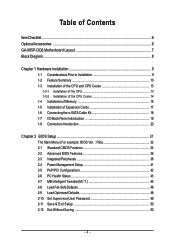
Table of Contents ItemChecklist ...6 OptionalAccessories ...6 GA-965P-DQ6 Motherboard Layout 7 Block Diagram ...8 Chapter 1 Hardware Installation 9 1-1 Considerations Prior to Installation 9 1-2 Feature Summary 10 1-3 Installation of the CPU and CPU Cooler 13 1-3-1 Installation of the ...
Table of Contents ItemChecklist ...6 OptionalAccessories ...6 GA-965P-DQ6 Motherboard Layout 7 Block Diagram ...8 Chapter 1 Hardware Installation 9 1-1 Considerations Prior to Installation 9 1-2 Feature Summary 10 1-3 Installation of the CPU and CPU Cooler 13 1-3-1 Installation of the ...

Manual
Page 7
GA-965P-DQ6 Motherboard Layout KB_MS COAXIAL OPTICAL ATX_12V_2X LGA775 PWR_FAN PCIE_12V ATX COM LPT 1394 USB GA-965P-DQ6 LAN USB AUDIO BATTERY CPU_FAN CLR_CMOS Intel® P965 F_AUDIO PCIE_1 FDD Marvell 8056 PCIE_16_1 DDRII1 DDRII2 DDRII3 DDRII4 PCIE_2 CODEC PCIE_3 CD_IN PCIE_16_2 PCI1 IT8718 PCI2 TPM SPDIF_IN BP_BIOS MAIN_BIOS SATAII0 CI SYS_FAN Intel® ICH8R TSB43AB23 SATAII4 SATAII1 SATAII2 SATAII5 SATAII3 GIGABYTE SATA2 IDE GSATAII1 GSATAII0 F_USB1 F_USB2 F_USB3 F1_1394 F2_1394 PWR_LED F_PANEL - 7 -
GA-965P-DQ6 Motherboard Layout KB_MS COAXIAL OPTICAL ATX_12V_2X LGA775 PWR_FAN PCIE_12V ATX COM LPT 1394 USB GA-965P-DQ6 LAN USB AUDIO BATTERY CPU_FAN CLR_CMOS Intel® P965 F_AUDIO PCIE_1 FDD Marvell 8056 PCIE_16_1 DDRII1 DDRII2 DDRII3 DDRII4 PCIE_2 CODEC PCIE_3 CD_IN PCIE_16_2 PCI1 IT8718 PCI2 TPM SPDIF_IN BP_BIOS MAIN_BIOS SATAII0 CI SYS_FAN Intel® ICH8R TSB43AB23 SATAII4 SATAII1 SATAII2 SATAII5 SATAII3 GIGABYTE SATA2 IDE GSATAII1 GSATAII0 F_USB1 F_USB2 F_USB3 F1_1394 F2_1394 PWR_LED F_PANEL - 7 -
Manual
Page 8
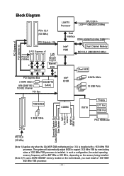
... MHz) x1 x1 x1 Switch LAN RJ45 Marvell 8056 x1 PCI Express Bus 2 SATA 3Gb/s ATA-33/66/100/ 133 IDE Channel PCI Bus GIGABYTE SATA2 LGA775 Processor CPU CLK+/(333(Note 1)/266/200/133 MHz) Host Interface DDRII 800/667/533 MHz DIMM(Note 2) Intel® P965 Dual Channel.../Subwoofer Speaker Out Side Speaker Out MIC Line-Out Line-In SPDIF In SPDIF Out 2 PCI PCI CLK (33 MHz) (Note 1) Applies only when the GA-965P-DQ6 motherboard (rev. 3.3) is installed. In such a configuration, the actual operating memory frequency will automatically adjust BIOS to support 1333 MHz FSB by overclocking when a...
... MHz) x1 x1 x1 Switch LAN RJ45 Marvell 8056 x1 PCI Express Bus 2 SATA 3Gb/s ATA-33/66/100/ 133 IDE Channel PCI Bus GIGABYTE SATA2 LGA775 Processor CPU CLK+/(333(Note 1)/266/200/133 MHz) Host Interface DDRII 800/667/533 MHz DIMM(Note 2) Intel® P965 Dual Channel.../Subwoofer Speaker Out Side Speaker Out MIC Line-Out Line-In SPDIF In SPDIF Out 2 PCI PCI CLK (33 MHz) (Note 1) Applies only when the GA-965P-DQ6 motherboard (rev. 3.3) is installed. In such a configuration, the actual operating memory frequency will automatically adjust BIOS to support 1333 MHz FSB by overclocking when a...
Manual
Page 10
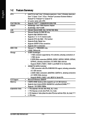
Supports RAID 0, RAID 1 and JBOD for Serial ATA Š GIGABYTE SATA2 Controller - 1 IDE connectors with ATA-33/66/100/133 support, allowing connection of 2 IDE devices - 2 SATA 3Gb/s connectors (GSATAII0, GSATAII1), allowing connection of 6 SATA ... / CoreTM 2 Duo / Pentium® processor Extreme Edition / Pentium® D / Pentium® 4 / Celeron® D Š L2 cache varies with the PCIE_16_2 slot) (Note 3) Š 2 PCI slots GA-965P-DQ6 Motherboard - 10 -
Supports RAID 0, RAID 1 and JBOD for Serial ATA Š GIGABYTE SATA2 Controller - 1 IDE connectors with ATA-33/66/100/133 support, allowing connection of 2 IDE devices - 2 SATA 3Gb/s connectors (GSATAII0, GSATAII1), allowing connection of 6 SATA ... / CoreTM 2 Duo / Pentium® processor Extreme Edition / Pentium® D / Pentium® 4 / Celeron® D Š L2 cache varies with the PCIE_16_2 slot) (Note 3) Š 2 PCI slots GA-965P-DQ6 Motherboard - 10 -
Manual
Page 12
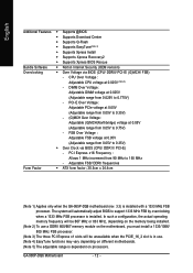
...voltage at 0.05V (Adjustable range from 0.05V to 0.35V) - (G)MCH Over Voltage : Adjustable (G)MCH(Northbridge) voltage at 0.025V (Note 5) - GA-965P-DQ6 Motherboard - 12 - English Additional Features Š Supports @BIOS Š Supports Download Center Š Supports Q-Flash Š Supports EasyTune(Note 4) ...Adjustable FSB/ DDRII frequencies Form Factor Š ATX form factor; 30.5cm x 24.4cm (Note 1) Applies only when the GA-965P-DQ6 motherboard (rev. 3.3) is dependent on different motherboards. (Note 5) The adjustable range is installed with a 1333 MHz FSB processor....
...voltage at 0.05V (Adjustable range from 0.05V to 0.35V) - (G)MCH Over Voltage : Adjustable (G)MCH(Northbridge) voltage at 0.025V (Note 5) - GA-965P-DQ6 Motherboard - 12 - English Additional Features Š Supports @BIOS Š Supports Download Center Š Supports Q-Flash Š Supports EasyTune(Note 4) ...Adjustable FSB/ DDRII frequencies Form Factor Š ATX form factor; 30.5cm x 24.4cm (Note 1) Applies only when the GA-965P-DQ6 motherboard (rev. 3.3) is dependent on different motherboards. (Note 5) The adjustable range is installed with a 1333 MHz FSB processor....
Manual
Page 14
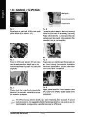
....1 Please apply an even layer of CPU cooler paste on the surface of the CPU cooler to the CPU fan header located on the motherboard. GA-965P-DQ6 Motherboard - 14 - Fig. 6 Finally, please attach the power connector of the installed CPU. To prevent such an occurrence, it is to the CPU as the...
....1 Please apply an even layer of CPU cooler paste on the surface of the CPU cooler to the CPU fan header located on the motherboard. GA-965P-DQ6 Motherboard - 14 - Fig. 6 Finally, please attach the power connector of the installed CPU. To prevent such an occurrence, it is to the CPU as the...
Manual
Page 16
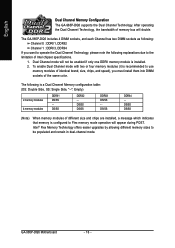
Dual Channel mode will not be populated and remain in dual-channel mode. DS/SS DS/SS DDRII3 DS/SS - The GA-965P-DQ6 includes 4 DIMM sockets, and each Channel has two DIMM sockets as following: Channel 0 : DDRII1, DDRII2 Channel 1 : DDRII3, DDRII4 If you must install them ... different memory sizes to be enabled if only one DDRII memory module is recommended to use memory modules of memory bus will appear during POST. GA-965P-DQ6 Motherboard - 16 - DS/SS DDRII2 - DS/SS DDRII4 - After operating the Dual Channel Technology, the bandwidth of identical brand, size, chips, and speed), ...
Dual Channel mode will not be populated and remain in dual-channel mode. DS/SS DS/SS DDRII3 DS/SS - The GA-965P-DQ6 includes 4 DIMM sockets, and each Channel has two DIMM sockets as following: Channel 0 : DDRII1, DDRII2 Channel 1 : DDRII3, DDRII4 If you must install them ... different memory sizes to be enabled if only one DDRII memory module is recommended to use memory modules of memory bus will appear during POST. GA-965P-DQ6 Motherboard - 16 - DS/SS DDRII2 - DS/SS DDRII4 - After operating the Dual Channel Technology, the bandwidth of identical brand, size, chips, and speed), ...

Manual
Page 18
... device(s) to your system by expanding the internal SATA port(s) to the chassis back panel. • Turn off the power of the external enclosure. supply. GA-965P-DQ6 Motherboard - 18 - Connect the other ends of the cable from the bracket to the SATA port on the power supply before installing or removing the...
... device(s) to your system by expanding the internal SATA port(s) to the chassis back panel. • Turn off the power of the external enclosure. supply. GA-965P-DQ6 Motherboard - 18 - Connect the other ends of the cable from the bracket to the SATA port on the power supply before installing or removing the...
Manual
Page 20
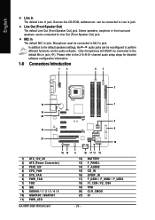
... 1 4 63 2 12 7 14 20 9 15 8 21 10 16 19 1) ATX_12V_2X 2) ATX (Power Connector) 3) PCIE_12V 4) CPU_FAN 5) SYS_FAN 6) PWR_FAN 7) FDD 8) IDE 9) SATAII0 / 1 / 2 / 3 / 4 / 5 10) GSATAII0 / GSATAII1 11) PWR_LED GA-965P-DQ6 Motherboard 5 18 17 11 13 12) BATTERY 13) F_PANEL 14) F_AUDIO 15) CD_IN 16) SPDIF_IN 17) F_USB1 / F_USB2 / F_USB3 18) F1_1394 / F2_1394 19) TPM 20...
... 1 4 63 2 12 7 14 20 9 15 8 21 10 16 19 1) ATX_12V_2X 2) ATX (Power Connector) 3) PCIE_12V 4) CPU_FAN 5) SYS_FAN 6) PWR_FAN 7) FDD 8) IDE 9) SATAII0 / 1 / 2 / 3 / 4 / 5 10) GSATAII0 / GSATAII1 11) PWR_LED GA-965P-DQ6 Motherboard 5 18 17 11 13 12) BATTERY 13) F_PANEL 14) F_AUDIO 15) CD_IN 16) SPDIF_IN 17) F_USB1 / F_USB2 / F_USB3 18) F1_1394 / F2_1394 19) TPM 20...
Manual
Page 22
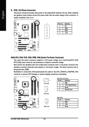
... extra power to the onboard PCI Express x16 slot. Definition 1 GND 2 +12V / Speed Control 3 Sense 4 Speed Control 1 PWR_FAN PWR_FAN : Pin No. 1 2 3 Definition GND +12V Sense GA-965P-DQ6 Motherboard - 22 - A red power connector wire indicates a positive connection and requires a +12V power voltage. The black connector wire is the ground wire (GND). Definition 1 NC...
... extra power to the onboard PCI Express x16 slot. Definition 1 GND 2 +12V / Speed Control 3 Sense 4 Speed Control 1 PWR_FAN PWR_FAN : Pin No. 1 2 3 Definition GND +12V Sense GA-965P-DQ6 Motherboard - 22 - A red power connector wire indicates a positive connection and requires a +12V power voltage. The black connector wire is the ground wire (GND). Definition 1 NC...
Manual
Page 24
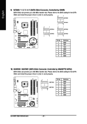
... BIOS setting for the SATA 3Gb/s and install the proper driver in order to work properly. 7 1 Pin No. English 9) SATAII0 / 1 / 2 / 3 / 4 / 5 (SATA 3Gb/s Connector, Controlled by GIGABYTE SATA2) SATA 3Gb/s can provide up to 300 MB/s transfer rate. Please refer to the BIOS setting for the SATA 3Gb/s and install the proper... 3Gb/s Connector, Controlled by ICH8R) SATA 3Gb/s can provide up to 300 MB/s transfer rate. Definition GSATAII0 1 GND 2 TXP 3 TXN GSATAII1 4 GND 1 7 5 RXN 6 RXP 7 GND GA-965P-DQ6 Motherboard - 24 -
... BIOS setting for the SATA 3Gb/s and install the proper driver in order to work properly. 7 1 Pin No. English 9) SATAII0 / 1 / 2 / 3 / 4 / 5 (SATA 3Gb/s Connector, Controlled by GIGABYTE SATA2) SATA 3Gb/s can provide up to 300 MB/s transfer rate. Please refer to the BIOS setting for the SATA 3Gb/s and install the proper... 3Gb/s Connector, Controlled by ICH8R) SATA 3Gb/s can provide up to 300 MB/s transfer rate. Definition GSATAII0 1 GND 2 TXP 3 TXN GSATAII1 4 GND 1 7 5 RXN 6 RXP 7 GND GA-965P-DQ6 Motherboard - 24 -

Manual
Page 26
...: Normal Close: Power On/Off Pin 1: Power Pin 2- Pin 3: NC Pin 4: Data(-) Pin 1: LED anode(+) Pin 2: LED cathode(-) Open: Normal Close: Reset Hardware System NC GA-965P-DQ6 Motherboard - 26 - of your chassis front panel to the F_PANEL connector according to the pin assignment below. PW+ PWSPEAK+ SPEAK- 2 20 1 19 HD+ HD- English...
...: Normal Close: Power On/Off Pin 1: Power Pin 2- Pin 3: NC Pin 4: Data(-) Pin 1: LED anode(+) Pin 2: LED cathode(-) Open: Normal Close: Reset Hardware System NC GA-965P-DQ6 Motherboard - 26 - of your chassis front panel to the F_PANEL connector according to the pin assignment below. PW+ PWSPEAK+ SPEAK- 2 20 1 19 HD+ HD- English...
Manual
Page 28
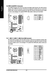
... when your local dealer. 12 9 10 Pin No. 1 2 3 4 5 6 7 8 9 10 Definition Power (5V) Power (5V) USB DXUSB DyUSB DX+ USB Dy+ GND GND No Pin NC GA-965P-DQ6 Motherboard - 28 - For optional front USB cable, please contact your device has digital output function. Check the pin assignment carefully while you connect the front...
... when your local dealer. 12 9 10 Pin No. 1 2 3 4 5 6 7 8 9 10 Definition Power (5V) Power (5V) USB DXUSB DyUSB DX+ USB Dy+ GND GND No Pin NC GA-965P-DQ6 Motherboard - 28 - For optional front USB cable, please contact your device has digital output function. Check the pin assignment carefully while you connect the front...
Manual
Page 30
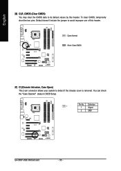
Open: Normal Short: Clear CMOS 21) CI (Chassis Intrusion, Case Open) This 2-pin connector allows your system to avoid improper use of this header. Pin No. You can check the "Case Opened" status in BIOS Setup. English 20) CLR_CMOS (Clear CMOS) You may clear the CMOS data to its default values by this header. Definition 1 1 Signal 2 GND GA-965P-DQ6 Motherboard - 30 - Default doesn't include the jumper to detect if the chassis cover is removed. To clear CMOS, temporarily short the two pins.
Open: Normal Short: Clear CMOS 21) CI (Chassis Intrusion, Case Open) This 2-pin connector allows your system to avoid improper use of this header. Pin No. You can check the "Case Opened" status in BIOS Setup. English 20) CLR_CMOS (Clear CMOS) You may clear the CMOS data to its default values by this header. Definition 1 1 Signal 2 GND GA-965P-DQ6 Motherboard - 30 - Default doesn't include the jumper to detect if the chassis cover is removed. To clear CMOS, temporarily short the two pins.
Manual
Page 32
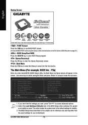
... POST screen. (To show the BIOS POST screen at system startup, refer to the instructions on the Full Screen LOGO Show item on the screen. GA-965P-DQ6 Motherboard - 32 - Use arrow keys to select among the items and press to accept or enter the sub-menu. CMOS Setup Utility-Copyright (C) 1984-2006...
... POST screen. (To show the BIOS POST screen at system startup, refer to the instructions on the Full Screen LOGO Show item on the screen. GA-965P-DQ6 Motherboard - 32 - Use arrow keys to select among the items and press to accept or enter the sub-menu. CMOS Setup Utility-Copyright (C) 1984-2006...
Manual
Page 34
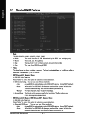
... select this if no IDE/SATA devices are used and the system will skip the automatic detection step and allow for faster system start up . GA-965P-DQ6 Motherboard - 34 - Day The day, from 2000 through 2099 Time The times format in . IDE Device Setup. Access Mode Use this option for the hard...
... select this if no IDE/SATA devices are used and the system will skip the automatic detection step and allow for faster system start up . GA-965P-DQ6 Motherboard - 34 - Day The day, from 2000 through 2099 Time The times format in . IDE Device Setup. Access Mode Use this option for the hard...
Manual
Page 36
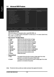
... Disk Select your boot device priority by Hard Disk. CDROM Select your boot device priority by CDROM. Select your boot device priority by USB-CDROM. GA-965P-DQ6 Motherboard - 36 - to move it up when you install a processor that supports this menu. Password Check Setup The system will boot but will not access...
... Disk Select your boot device priority by Hard Disk. CDROM Select your boot device priority by CDROM. Select your boot device priority by USB-CDROM. GA-965P-DQ6 Motherboard - 36 - to move it up when you install a processor that supports this menu. Password Check Setup The system will boot but will not access...
Manual
Page 38
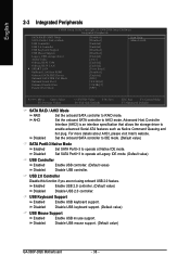
... Enabled Disabled Enable USB controller. (Default value) Disable USB controller. For more details about AHCI, please visit Intel's website. Disable USB mouse support. (Default value) GA-965P-DQ6 Motherboard - 38 - USB 2.0 Controller Disable this function if you are not using onboard USB 2.0 feature. USB Keyboard Support Enabled Disabled Enable USB keyboard support.
... Enabled Disabled Enable USB controller. (Default value) Disable USB controller. For more details about AHCI, please visit Intel's website. Disable USB mouse support. (Default value) GA-965P-DQ6 Motherboard - 38 - USB 2.0 Controller Disable this function if you are not using onboard USB 2.0 feature. USB Keyboard Support Enabled Disabled Enable USB keyboard support.

