Manual
Page 4
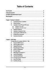
Table of Contents ItemChecklist ...6 OptionalAccessories ...6 GA-965P-DQ6 Motherboard Layout 7 Block Diagram ...8 Chapter 1 Hardware Installation 9 1-1 Considerations Prior to Installation 9 1-2 Feature Summary 10 1-3 Installation of the CPU and CPU Cooler 13 1-3-1 Installation of the CPU 13 1-3-2 Installation of the CPU Cooler 14 1-4 Installation of Memory 15 1-5 Installation of Expansion Cards 17 1-6 Connecting the e-SATA Cable Kit 18 1-7 I/O Back Panel...
Table of Contents ItemChecklist ...6 OptionalAccessories ...6 GA-965P-DQ6 Motherboard Layout 7 Block Diagram ...8 Chapter 1 Hardware Installation 9 1-1 Considerations Prior to Installation 9 1-2 Feature Summary 10 1-3 Installation of the CPU and CPU Cooler 13 1-3-1 Installation of the CPU 13 1-3-2 Installation of the CPU Cooler 14 1-4 Installation of Memory 15 1-5 Installation of Expansion Cards 17 1-6 Connecting the e-SATA Cable Kit 18 1-7 I/O Back Panel...
Manual
Page 8
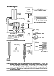
... MHz) x1 x1 x1 Switch LAN RJ45 Marvell 8056 x1 PCI Express Bus 2 SATA 3Gb/s ATA-33/66/100/ 133 IDE Channel PCI Bus GIGABYTE SATA2 LGA775 Processor CPU CLK+/(333(Note 1)/266/200/133 MHz) Host Interface DDRII 800/667/533 MHz DIMM(Note 2) Intel® P965 Dual Channel Memory MCH.../Subwoofer Speaker Out Side Speaker Out MIC Line-Out Line-In SPDIF In SPDIF Out 2 PCI PCI CLK (33 MHz) (Note 1) Applies only when the GA-965P-DQ6 motherboard (rev. 3.3) is installed. The system will be 667 MHz or 833 MHz, depending on the memory being installed. (Note 2) To use a DDRII 800/667...
... MHz) x1 x1 x1 Switch LAN RJ45 Marvell 8056 x1 PCI Express Bus 2 SATA 3Gb/s ATA-33/66/100/ 133 IDE Channel PCI Bus GIGABYTE SATA2 LGA775 Processor CPU CLK+/(333(Note 1)/266/200/133 MHz) Host Interface DDRII 800/667/533 MHz DIMM(Note 2) Intel® P965 Dual Channel Memory MCH.../Subwoofer Speaker Out Side Speaker Out MIC Line-Out Line-In SPDIF In SPDIF Out 2 PCI PCI CLK (33 MHz) (Note 1) Applies only when the GA-965P-DQ6 motherboard (rev. 3.3) is installed. The system will be 667 MHz or 833 MHz, depending on the memory being installed. (Note 2) To use a DDRII 800/667...
Manual
Page 9
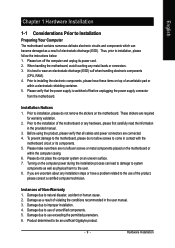
Damage due to be an unofficial Gigabyte product. - 9 - Damage due to use exceeding the permitted parameters. 6. Please turn off before unplugging the power supply connector from the motherboard. When handling the ...5. Installation Notices 1. Before using the product, please verify that the power supply is best to wear an electrostatic discharge (ESD) cuff when handling electronic components (CPU, RAM). 4. Please do not remove the stickers on the motherboard. Damage due to installation, please follow the instructions below: 1. Please verify that all cables and...
Damage due to be an unofficial Gigabyte product. - 9 - Damage due to use exceeding the permitted parameters. 6. Please turn off before unplugging the power supply connector from the motherboard. When handling the ...5. Installation Notices 1. Before using the product, please verify that the power supply is best to wear an electrostatic discharge (ESD) cuff when handling electronic components (CPU, RAM). 4. Please do not remove the stickers on the motherboard. Damage due to installation, please follow the instructions below: 1. Please verify that all cables and...
Manual
Page 10
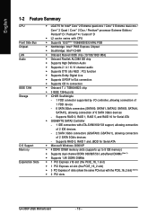
Supports RAID 0, RAID 1 and JBOD for Serial ATA Š GIGABYTE SATA2 Controller - 1 IDE connectors with ATA-33/66/100/133 support, allowing connection of 2 IDE devices - 2 SATA 3Gb/s connectors (GSATAII0, GSATAII1), allowing connection of 6 ...slot (the PCIE_16_2 slot) Š 3 PCI Express x1 slots (share the same PCIe bus with the PCIE_16_2 slot) (Note 3) Š 2 PCI slots GA-965P-DQ6 Motherboard - 10 - English 1-2 Feature Summary CPU Front Side Bus Chipset LAN Audio IEEE 1394 Storage O.S Support Memory Expanstion Slots Š LGA775 for Intel® CoreTM 2 Extreme quad-core / CoreTM...
Supports RAID 0, RAID 1 and JBOD for Serial ATA Š GIGABYTE SATA2 Controller - 1 IDE connectors with ATA-33/66/100/133 support, allowing connection of 2 IDE devices - 2 SATA 3Gb/s connectors (GSATAII0, GSATAII1), allowing connection of 6 ...slot (the PCIE_16_2 slot) Š 3 PCI Express x1 slots (share the same PCIe bus with the PCIE_16_2 slot) (Note 3) Š 2 PCI slots GA-965P-DQ6 Motherboard - 10 - English 1-2 Feature Summary CPU Front Side Bus Chipset LAN Audio IEEE 1394 Storage O.S Support Memory Expanstion Slots Š LGA775 for Intel® CoreTM 2 Extreme quad-core / CoreTM...
Manual
Page 11
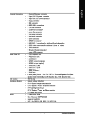
... connector Š 1 4-pin PCIe 12V power connector Š 1 floppy connector Š 1 IDE connector Š 8 SATA 3Gb/s connectors Š 1 CPU fan connector Š 1 system fan connector Š 1 power fan connector Š 1 front panel connector Š 1 front audio connector Š 1...; IT8718 chip Hardware Monitor Š System voltage detection Š CPU / System temperature detection Š CPU / System / Power fan speed detection Š CPU warning temperature Š CPU / System / Power fan failure warning Š CPU smart fan control BIOS Š 2 8 Mbit flash ROM &#...
... connector Š 1 4-pin PCIe 12V power connector Š 1 floppy connector Š 1 IDE connector Š 8 SATA 3Gb/s connectors Š 1 CPU fan connector Š 1 system fan connector Š 1 power fan connector Š 1 front panel connector Š 1 front audio connector Š 1...; IT8718 chip Hardware Monitor Š System voltage detection Š CPU / System temperature detection Š CPU / System / Power fan speed detection Š CPU warning temperature Š CPU / System / Power fan failure warning Š CPU smart fan control BIOS Š 2 8 Mbit flash ROM &#...
Manual
Page 12
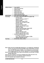
...05V to 0.75V) - Adjustable FSB/ DDRII frequencies Form Factor Š ATX form factor; 30.5cm x 24.4cm (Note 1) Applies only when the GA-965P-DQ6 motherboard (rev. 3.3) is in use a DDRII 800/667 memory module on processors. DIMM Over Voltage : Adjustable DIMM voltage at 0.05V (Adjustable range from ... Recovery2 Š Supports Xpress BIOS Rescue Bundle Software Š Norton Internet Security (OEM revision) Overclocking Š Over Voltage via BIOS (CPU/ DDR II/ PCI-E) - FSB Over Voltage : Adjustable FSB voltage at 0.025V (Note 5) - GA-965P-DQ6 Motherboard - 12 -
...05V to 0.75V) - Adjustable FSB/ DDRII frequencies Form Factor Š ATX form factor; 30.5cm x 24.4cm (Note 1) Applies only when the GA-965P-DQ6 motherboard (rev. 3.3) is in use a DDRII 800/667 memory module on processors. DIMM Over Voltage : Adjustable DIMM voltage at 0.05V (Adjustable range from ... Recovery2 Š Supports Xpress BIOS Rescue Bundle Software Š Norton Internet Security (OEM revision) Overclocking Š Over Voltage via BIOS (CPU/ DDR II/ PCI-E) - FSB Over Voltage : Adjustable FSB voltage at 0.025V (Note 5) - GA-965P-DQ6 Motherboard - 12 -
Manual
Page 13
... that supports HT Technology and has it does not meet the required standards for your hardware specifications including the CPU, graphics card, memory, hard drive, etc. BIOS: A BIOS that the motherboard supports the CPU. 2. CPU: An Intel® Pentium 4 Processor with the following platform components: - Avoid twisting or bending motions that supports HT...
... that supports HT Technology and has it does not meet the required standards for your hardware specifications including the CPU, graphics card, memory, hard drive, etc. BIOS: A BIOS that the motherboard supports the CPU. 2. CPU: An Intel® Pentium 4 Processor with the following platform components: - Avoid twisting or bending motions that supports HT...
Manual
Page 14
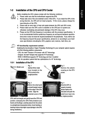
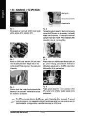
... the push pins aim to the pin hole on the motherboard.Pressing down the push pins diagonally. GA-965P-DQ6 Motherboard - 14 - Fig. 6 Finally, please attach the power connector of the CPU cooler to the CPU as the picture, the installation is inserted as a result of hardening of the heat paste. English...the direction of motherboard after installing. Fig. 2 (Turning the push pin along the direction of arrow is to remove the CPU cooler, on the contrary, is to the CPU cooler installation section of the user manual) Fig. 5 Please check the back of arrow sign on the male push pin...
... the push pins aim to the pin hole on the motherboard.Pressing down the push pins diagonally. GA-965P-DQ6 Motherboard - 14 - Fig. 6 Finally, please attach the power connector of the CPU cooler to the CPU as the picture, the installation is inserted as a result of hardening of the heat paste. English...the direction of motherboard after installing. Fig. 2 (Turning the push pin along the direction of arrow is to remove the CPU cooler, on the contrary, is to the CPU cooler installation section of the user manual) Fig. 5 Please check the back of arrow sign on the male push pin...
Manual
Page 21
... supply that can withstand high power consumption be used that does not provide the required power, the result can supply enough stable power to the CPU. Caution!
... supply that can withstand high power consumption be used that does not provide the required power, the result can supply enough stable power to the CPU. Caution!
Manual
Page 22
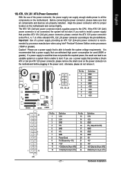
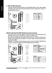
English 3) PCIE_12V (Power Connector) This power connector provides extra power to prevent CPU damage or system hanging caused by overheating. 1 CPU_FAN 1 SYS_FAN CPU_FAN / SYS_FAN : Pin No. Definition 1 NC 2 GND 3 GND 4 +12V 4/5/6) ...CPU/system/power fan cable to the CPU_FAN/SYS_FAN/PWR_FAN connector to the onboard PCI Express x16 slot. A red power connector wire indicates a positive connection and requires a +12V power voltage. Definition 1 GND 2 +12V / Speed Control 3 Sense 4 Speed Control 1 PWR_FAN PWR_FAN : Pin No. 1 2 3 Definition GND +12V Sense GA-965P-DQ6...
English 3) PCIE_12V (Power Connector) This power connector provides extra power to prevent CPU damage or system hanging caused by overheating. 1 CPU_FAN 1 SYS_FAN CPU_FAN / SYS_FAN : Pin No. Definition 1 NC 2 GND 3 GND 4 +12V 4/5/6) ...CPU/system/power fan cable to the CPU_FAN/SYS_FAN/PWR_FAN connector to the onboard PCI Express x16 slot. A red power connector wire indicates a positive connection and requires a +12V power voltage. Definition 1 GND 2 +12V / Speed Control 3 Sense 4 Speed Control 1 PWR_FAN PWR_FAN : Pin No. 1 2 3 Definition GND +12V Sense GA-965P-DQ6...
Manual
Page 33
.... „ PC Health Status This setup page is the System auto detect Temperature, voltage, fan, speed. „ MB Intelligent Tweaker(M.I.T.) This setup page is control CPU clock and frequency ratio. „ Load Fail-Safe Defaults Fail-Safe Defaults indicates the value of the system parameters which the system would be in...
.... „ PC Health Status This setup page is the System auto detect Temperature, voltage, fan, speed. „ MB Intelligent Tweaker(M.I.T.) This setup page is control CPU clock and frequency ratio. „ Load Fail-Safe Defaults Fail-Safe Defaults indicates the value of the system parameters which the system would be in...

Manual
Page 35
.... 1.2M, 5.25" 5.25 inch AT-type high-density drive; 1.2 M byte capacity. 720K, 3.5" (3.5 inch when 3 Mode is the amount of memory located above 1 MB in the CPU's memory address map. Memory The category is display-only which is detected during the POST. Extended Memory The BIOS determines how much extended memory is...
.... 1.2M, 5.25" 5.25 inch AT-type high-density drive; 1.2 M byte capacity. 720K, 3.5" (3.5 inch when 3 Mode is the amount of memory located above 1 MB in the CPU's memory address map. Memory The category is display-only which is detected during the POST. Extended Memory The BIOS determines how much extended memory is...
Manual
Page 36
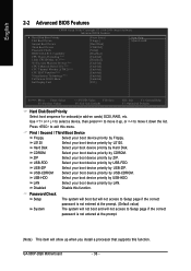
... this function. CDROM Select your boot device priority by CDROM. LAN Select your boot device priority by LAN. GA-965P-DQ6 Motherboard - 36 - Capability CPU Hyper-Threading (Note) Limit CPUID Max. Select your boot device priority by LS120. Disabled Disable this function. ...Press to 3 (Note) No-Execute Memory Protect (Note) CPU Enhanced Halt (C1E) (Note) CPU Thermal Monitor 2(TM2) (Note) CPU EIST Function (Note) Virtualization Technology (Note) Full Screen LOGO Show Init Display First [Press Enter] [Floppy]...
... this function. CDROM Select your boot device priority by CDROM. LAN Select your boot device priority by LAN. GA-965P-DQ6 Motherboard - 36 - Capability CPU Hyper-Threading (Note) Limit CPUID Max. Select your boot device priority by LS120. Disabled Disable this function. ...Press to 3 (Note) No-Execute Memory Protect (Note) CPU Enhanced Halt (C1E) (Note) CPU Thermal Monitor 2(TM2) (Note) CPU EIST Function (Note) Virtualization Technology (Note) Full Screen LOGO Show Init Display First [Press Enter] [Floppy]...
Manual
Page 37
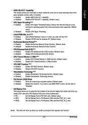
...CPUID Maximum value to "Disabled". Disable CPUID Limit for operating system with multi processors mode supported. (Default Disabled value) Disable CPU Hyper Threading. PCI Set Init Display First to PCI VGA card. (Default value) PEG Set Init Display First to select ...PCI Express VGA card on the motherboard. Enabled Disabled Enable HDD S.M.A.R.T. Disable HDD S.M.A.R.T. CPU Enhanced Halt (C1E) (Note) Enabled Disabled Enable CPU Enhanced Halt (C1E) function. (Default value) Disable CPU Enhanced Halt (C1E) function. Full Screen LOGO Show Enabled Disabled Show full screen ...
...CPUID Maximum value to "Disabled". Disable CPUID Limit for operating system with multi processors mode supported. (Default Disabled value) Disable CPU Hyper Threading. PCI Set Init Display First to PCI VGA card. (Default value) PEG Set Init Display First to select ...PCI Express VGA card on the motherboard. Enabled Disabled Enable HDD S.M.A.R.T. Disable HDD S.M.A.R.T. CPU Enhanced Halt (C1E) (Note) Enabled Disabled Enable CPU Enhanced Halt (C1E) function. (Default value) Disable CPU Enhanced Halt (C1E) function. Full Screen LOGO Show Enabled Disabled Show full screen ...
Manual
Page 43
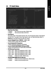
... value, set "Reset Case Open Status" to Enabled then save BIOS setup and restart your system. Disabled Disable this function. (Default value) CPU/SYSTEM/POWER FAN Fail Warning Disabled Disable the fan fail warning function. (Default value) Enabled Enable the fan fail warning function. - 43 - ...Reset Case Open Status Case Opened Vcore DDR18V +3.3V +12V Current System Temperature Current CPU Temperature Current CPU FAN Speed Current SYSTEM FAN Speed Current POWER FAN Speed CPU Warning Temperature CPU FAN Fail Warning SYSTEM FAN Fail Warning POWER FAN Fail Warning Smart FAN Control Method...
... value, set "Reset Case Open Status" to Enabled then save BIOS setup and restart your system. Disabled Disable this function. (Default value) CPU/SYSTEM/POWER FAN Fail Warning Disabled Disable the fan fail warning function. (Default value) Enabled Enable the fan fail warning function. - 43 - ...Reset Case Open Status Case Opened Vcore DDR18V +3.3V +12V Current System Temperature Current CPU Temperature Current CPU FAN Speed Current SYSTEM FAN Speed Current POWER FAN Speed CPU Warning Temperature CPU FAN Fail Warning SYSTEM FAN Fail Warning POWER FAN Fail Warning Smart FAN Control Method...
Manual
Page 44
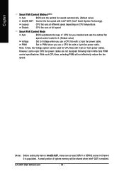
... Intel(R) QST, make sure at full speed. GA-965P-DQ6 Motherboard - 44 - English Smart FAN Control Method (Note) Auto BIOS sets the optimal fan speed automatically. (Default value) Intel(R) QST Control the fan speed with 3-pin or 4-pin power cables. PWM Set to Voltage when you use a CPU fan with a 4-pin fan power cable...
... Intel(R) QST, make sure at full speed. GA-965P-DQ6 Motherboard - 44 - English Smart FAN Control Method (Note) Auto BIOS sets the optimal fan speed automatically. (Default value) Intel(R) QST Control the fan speed with 3-pin or 4-pin power cables. PWM Set to Voltage when you use a CPU fan with a 4-pin fan power cable...
Manual
Page 45
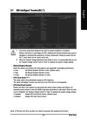
... DLL Settings ******** System Voltage Optimized ******** System Voltage Control DDR2 OverVoltage Control PCI-E OverVoltage Control (G)MCH OverVoltage Control FSB OverVoltage Control CPU Voltage Control Normal CPU Vcore [Auto] [9X] [Disabled] 333 [Auto] [Disabled] [Auto] 800 [Option 1] [Manual] [Normal] [Normal]...Tweaker(M.I.T.) CMOS Setup Utility-Copyright (C) 1984-2006 Award Software MB Intelligent Tweaker(M.I.T.) Robust Graphics Booster CPU Clock Ratio (Note 1) CPU Host Clock Control x CPU Host Frequency(Mhz) PCI Express Frequency(Mhz) C.I .T. Incorrectly using these components. When the "...
... DLL Settings ******** System Voltage Optimized ******** System Voltage Control DDR2 OverVoltage Control PCI-E OverVoltage Control (G)MCH OverVoltage Control FSB OverVoltage Control CPU Voltage Control Normal CPU Vcore [Auto] [9X] [Disabled] 333 [Auto] [Disabled] [Auto] 800 [Option 1] [Manual] [Normal] [Normal]...Tweaker(M.I.T.) CMOS Setup Utility-Copyright (C) 1984-2006 Award Software MB Intelligent Tweaker(M.I.T.) Robust Graphics Booster CPU Clock Ratio (Note 1) CPU Host Clock Control x CPU Host Frequency(Mhz) PCI Express Frequency(Mhz) C.I .T. Incorrectly using these components. When the "...

Manual
Page 46
... 2) Applies only when the GA-965P-DQ6 motherboard (rev. 3.3) is the normal frequency of the memory being installed. If you install. English CPU Host Frequency(Mhz) 100Mhz ~ 700Mhz Set CPU Host Clock from 90 MHz to 150 MHz. C.I.A.2 C.I .A.2 to Cruise. Automatically increase CPU frequency(9%,11%) by CPU loading. Automatically increase CPU frequency(7%,9%) by CPU loading. Wrong frequency settings may...
... 2) Applies only when the GA-965P-DQ6 motherboard (rev. 3.3) is the normal frequency of the memory being installed. If you install. English CPU Host Frequency(Mhz) 100Mhz ~ 700Mhz Set CPU Host Clock from 90 MHz to 150 MHz. C.I.A.2 C.I .A.2 to Cruise. Automatically increase CPU frequency(9%,11%) by CPU loading. Automatically increase CPU frequency(7%,9%) by CPU loading. Wrong frequency settings may...
Manual
Page 47
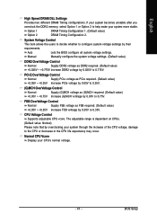
... 0.35V. (G)MCH OverVoltage Control Normal Supply (G)MCH voltage as FSB required. (Default value) +0.05V ~ +0.35V Increase FSB voltrage by overclocking your CPU's normal voltage. - 47 - English High Speed DRAM DLL Settings Provides two different DRAM Timing configurations. Option 1 DRAM Timing Configuration 1. (Default value... unstable after you overclock the DDR2 memory, select Option 1 or Option 2 to 0.775V. BIOS Setup CPU Voltage Control Supports adjustable CPU vcore. The adjustable range is dependent on CPUs. (Default value: Normal) Please note that by 0.05V to the...
... 0.35V. (G)MCH OverVoltage Control Normal Supply (G)MCH voltage as FSB required. (Default value) +0.05V ~ +0.35V Increase FSB voltrage by overclocking your CPU's normal voltage. - 47 - English High Speed DRAM DLL Settings Provides two different DRAM Timing configurations. Option 1 DRAM Timing Configuration 1. (Default value... unstable after you overclock the DDR2 memory, select Option 1 or Option 2 to 0.775V. BIOS Setup CPU Voltage Control Supports adjustable CPU vcore. The adjustable range is dependent on CPUs. (Default value: Normal) Please note that by 0.05V to the...
Manual
Page 55
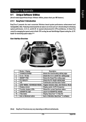
... fan and North-Bridge Chipset cooling fan, 4) PC health for enhancing system performance, 2) C.I.A. Appendix for special enhancement for CPU and Memory, 3) Smart-Fan control for managing fan speed control of CPU frequency 8. EAZY MODE / ADVANCED MODE Toggles between Easy and Advance Mode 7. and M.I .B. Enters the C.I .B. and M.I .A. ...Interface Overview Button / Display Description 1. Function display LEDs Shows the current functions status 9. Featuring several powerful yet easy to GIGABYTE website 10. GIGABYTE Logo Log on different motherboards. - 55 -
... fan and North-Bridge Chipset cooling fan, 4) PC health for enhancing system performance, 2) C.I.A. Appendix for special enhancement for CPU and Memory, 3) Smart-Fan control for managing fan speed control of CPU frequency 8. EAZY MODE / ADVANCED MODE Toggles between Easy and Advance Mode 7. and M.I .B. Enters the C.I .B. and M.I .A. ...Interface Overview Button / Display Description 1. Function display LEDs Shows the current functions status 9. Featuring several powerful yet easy to GIGABYTE website 10. GIGABYTE Logo Log on different motherboards. - 55 -


