Manual
Page 1
GA-945GCM-S2 GA-945GCMX-S2 Intel® CoreTM 2 Extreme dual-core / CoreTM 2 Duo / Intel® Pentium® D / Pentium® 4 / Celeron® D LGA775 Processor Motherboard User's Manual Rev. 6602 12ME-945CMX2R-6602R * The WEEE marking on the product indicates this product must not be disposed of with user's other household waste and must be handed over to a designated collection point for the recycling of waste electrical and electronic equipment!! * The WEEE marking applies only in European Union's member states.
GA-945GCM-S2 GA-945GCMX-S2 Intel® CoreTM 2 Extreme dual-core / CoreTM 2 Duo / Intel® Pentium® D / Pentium® 4 / Celeron® D LGA775 Processor Motherboard User's Manual Rev. 6602 12ME-945CMX2R-6602R * The WEEE marking on the product indicates this product must not be disposed of with user's other household waste and must be handed over to a designated collection point for the recycling of waste electrical and electronic equipment!! * The WEEE marking applies only in European Union's member states.
Manual
Page 2
Motherboard GA-945GCMX-S2 Mar. 23, 2007 Motherboard GA-945GCMX-S2 Mar. 23, 2007
Motherboard GA-945GCMX-S2 Mar. 23, 2007 Motherboard GA-945GCMX-S2 Mar. 23, 2007
Manual
Page 3
Motherboard GA-945GCM-S2 Jan. 12, 2007 Motherboard GA-945GCM-S2 Jan. 12, 2007
Motherboard GA-945GCM-S2 Jan. 12, 2007 Motherboard GA-945GCM-S2 Jan. 12, 2007
Manual
Page 5
Table of Contents ItemChecklist ...7 OptionalAccessories ...7 GA-945GCMX-S2 Motherboard Layout 8 GA-945GCM-S2 Motherboard Layout 9 Block Diagram ...10 Chapter 1 Hardware Installation 11 1-1 Considerations Prior to Installation 11 1-2 Feature Summary 12 1-3...1-5 Installation of Expansion Cards 18 1-6 I/O Back Panel Introduction 19 1-7 Connectors Introduction 20 Chapter 2 BIOS Setup 31 The Main Menu (For example: GA-945GCMX-S2 BIOS Ver. : F5a 32 2-1 Standard CMOS Features 34 2-2 Advanced BIOS Features 36 2-3 IntegratedPeripherals 38 2-4 Power Management Setup 42 2-5 PnP/PCI ...
Table of Contents ItemChecklist ...7 OptionalAccessories ...7 GA-945GCMX-S2 Motherboard Layout 8 GA-945GCM-S2 Motherboard Layout 9 Block Diagram ...10 Chapter 1 Hardware Installation 11 1-1 Considerations Prior to Installation 11 1-2 Feature Summary 12 1-3...1-5 Installation of Expansion Cards 18 1-6 I/O Back Panel Introduction 19 1-7 Connectors Introduction 20 Chapter 2 BIOS Setup 31 The Main Menu (For example: GA-945GCMX-S2 BIOS Ver. : F5a 32 2-1 Standard CMOS Features 34 2-2 Advanced BIOS Features 36 2-3 IntegratedPeripherals 38 2-4 Power Management Setup 42 2-5 PnP/PCI ...
Manual
Page 8
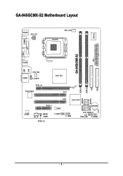
GA-945GCMX-S2 Motherboard Layout KB_MS ATX_12V CPU_FAN LGA775 IT8718 COMA LPT VGA GA-945GCMX-S2 ATX R_USB LAN USB AUDIO SYS_FAN F_AUDIO Intel® 945 DDRII1 DDRII2 IDE FDD PCIE_16 RTL8110SC PCI1 SATAII0 SATAII2 SATAII1 SATAII3 PCI2 Intel® ICH7 PCIE_4 BIOS CODEC CD_IN COMB SPDIF_IO F_USB1 F_USB2 BATTERY CLR_CMOS CI PWR_LED F_PANEL - 8 -
GA-945GCMX-S2 Motherboard Layout KB_MS ATX_12V CPU_FAN LGA775 IT8718 COMA LPT VGA GA-945GCMX-S2 ATX R_USB LAN USB AUDIO SYS_FAN F_AUDIO Intel® 945 DDRII1 DDRII2 IDE FDD PCIE_16 RTL8110SC PCI1 SATAII0 SATAII2 SATAII1 SATAII3 PCI2 Intel® ICH7 PCIE_4 BIOS CODEC CD_IN COMB SPDIF_IO F_USB1 F_USB2 BATTERY CLR_CMOS CI PWR_LED F_PANEL - 8 -
Manual
Page 9
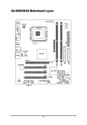
GA-945GCM-S2 Motherboard Layout KB_MS ATX_12V CPU_FAN LGA775 IT8718 COMA LPT VGA GA-945GCM-S2 ATX R_USB LAN USB AUDIO SYS_FAN F_AUDIO PCIE_16 RTL8110SC CODEC CD_IN COMB SPDIF_IO Intel® 945 DDRII1 DDRII2 IDE FDD PCI1 SATAII0 SATAII2 SATAII1 SATAII3 PCI2 Intel® ICH7 PCI3 BIOS F_USB1 F_USB2 BATTERY CLR_CMOS CI PWR_LED F_PANEL - 9 -
GA-945GCM-S2 Motherboard Layout KB_MS ATX_12V CPU_FAN LGA775 IT8718 COMA LPT VGA GA-945GCM-S2 ATX R_USB LAN USB AUDIO SYS_FAN F_AUDIO PCIE_16 RTL8110SC CODEC CD_IN COMB SPDIF_IO Intel® 945 DDRII1 DDRII2 IDE FDD PCI1 SATAII0 SATAII2 SATAII1 SATAII3 PCI2 Intel® ICH7 PCI3 BIOS F_USB1 F_USB2 BATTERY CLR_CMOS CI PWR_LED F_PANEL - 9 -
Manual
Page 11
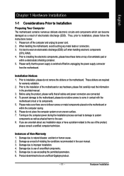
...when handling electronic components (CPU, RAM). 4. English Chapter 1 Hardware Installation 1-1 Considerations Prior to Installation Preparing Your Computer The motherboard contains numerous delicate electronic circuits and components which can lead to damage to system components as well as a result of electrostatic discharge... (ESD). Thus, prior to be an unofficial Gigabyte product. - 11 - Please verify that all cables and power connectors are required for warranty validation. 2. Prior to installation...
...when handling electronic components (CPU, RAM). 4. English Chapter 1 Hardware Installation 1-1 Considerations Prior to Installation Preparing Your Computer The motherboard contains numerous delicate electronic circuits and components which can lead to damage to system components as well as a result of electrostatic discharge... (ESD). Thus, prior to be an unofficial Gigabyte product. - 11 - Please verify that all cables and power connectors are required for warranty validation. 2. Prior to installation...
Manual
Page 12
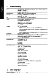
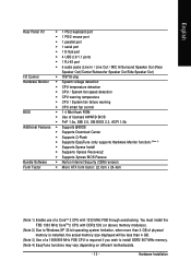
GA-945GCM(X)-S2 Motherboard - 12 - Only for GA-945GCMX-S2. English 1-2 Feature Summary CPU Š LGA775 for Intel® CoreTM 2 Extreme dual-core / CoreTM 2 Duo / Pentium® D / Pentium® 4 / Celeron® D Š L2 cache varies ...; 1 S/PDIF In/Out connector Š 2 USB 2.0/1.1 connectors for additional 4 ports by cables Š 1 COMB connector Š 1 Chassis Intrusion connector Š 1 power LED connector Only for GA-945GCM-S2.
GA-945GCM(X)-S2 Motherboard - 12 - Only for GA-945GCMX-S2. English 1-2 Feature Summary CPU Š LGA775 for Intel® CoreTM 2 Extreme dual-core / CoreTM 2 Duo / Pentium® D / Pentium® 4 / Celeron® D Š L2 cache varies ...; 1 S/PDIF In/Out connector Š 2 USB 2.0/1.1 connectors for additional 4 ports by cables Š 1 COMB connector Š 1 Chassis Intrusion connector Š 1 power LED connector Only for GA-945GCM-S2.
Manual
Page 13
... of a 1066/800 MHz FSB CPU is required if you wish to install DDR2 667 MHz memory. (Note 4) EasyTune functions may vary depending on different motherboards. - 13 -
... of a 1066/800 MHz FSB CPU is required if you wish to install DDR2 667 MHz memory. (Note 4) EasyTune functions may vary depending on different motherboards. - 13 -
Manual
Page 14
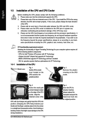
... the one indented corner of the CPU. 3. Please set the CPU host frequency in a straight and downwards motion. Chipset: An Intel® Chipset that the motherboard supports the CPU. 2. OS: An operation system that the system bus frequency be set the frequency beyond hardware specifications since it does not meet the... Intel® Pentium 4 Processor with the processor specifications. Fig. 3 Notice the small gold colored triangle located on the CPU prior to the CPU during installation.) GA-945GCM(X)-S2 Motherboard - 14 -
... the one indented corner of the CPU. 3. Please set the CPU host frequency in a straight and downwards motion. Chipset: An Intel® Chipset that the motherboard supports the CPU. 2. OS: An operation system that the system bus frequency be set the frequency beyond hardware specifications since it does not meet the... Intel® Pentium 4 Processor with the processor specifications. Fig. 3 Notice the small gold colored triangle located on the CPU prior to the CPU during installation.) GA-945GCM(X)-S2 Motherboard - 14 -
Manual
Page 15
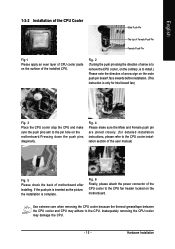
...'t face inwards before installation. (This instruction is complete. Fig. 4 Please make sure the push pins aim to install.) Please note the direction of motherboard after installing. If the push pin is inserted as the picture, the installation is only for Intel boxed fan) Fig. 3 Place the CPU cooler..., please refer to the CPU cooler installation section of the user manual) Fig. 5 Please check the back of arrow sign on the motherboard.Pressing down the push pins diagonally. Use extreme care when removing the CPU cooler because the thermal grease/tape between the CPU cooler and ...
...'t face inwards before installation. (This instruction is complete. Fig. 4 Please make sure the push pins aim to install.) Please note the direction of motherboard after installing. If the push pin is inserted as the picture, the installation is only for Intel boxed fan) Fig. 3 Place the CPU cooler..., please refer to the CPU cooler installation section of the user manual) Fig. 5 Please check the back of arrow sign on the motherboard.Pressing down the push pins diagonally. Use extreme care when removing the CPU cooler because the thermal grease/tape between the CPU cooler and ...
Manual
Page 16
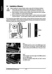
...modules are unable to remove the DIMM module. Reverse the installation steps when you are designed so that the memory used . 2. GA-945GCM(X)-S2 Motherboard - 16 - Before installing or removing memory modules, please make sure that they can be installed in one direction. It is ...recommended that the computer power is supported by the motherboard. Please make sure that memory of similar capacity, specifications and brand be inserted ...
...modules are unable to remove the DIMM module. Reverse the installation steps when you are designed so that the memory used . 2. GA-945GCM(X)-S2 Motherboard - 16 - Before installing or removing memory modules, please make sure that they can be installed in one direction. It is ...recommended that the computer power is supported by the motherboard. Please make sure that memory of similar capacity, specifications and brand be inserted ...
Manual
Page 18
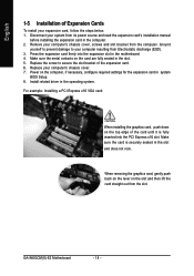
... to secure the slot bracket of the card until it is securely seated in the slot and does not rock. Install related driver in the motherboard. 4. Remove your computer resulting from Electrostatic discharge (ESD). 3. Power on the card are fully seated in the slot. 5. For example: Installing a PCI ...When removing the graphics card, gently push back on the lever on the top edge of the expansion card. 6. Replace your computer's chassis cover. 7. GA-945GCM(X)-S2 Motherboard - 18 - Make sure the card is fully inserted into the expansion slot in the operating system.
... to secure the slot bracket of the card until it is securely seated in the slot and does not rock. Install related driver in the motherboard. 4. Remove your computer resulting from Electrostatic discharge (ESD). 3. Power on the card are fully seated in the slot. 5. For example: Installing a PCI ...When removing the graphics card, gently push back on the lever on the top edge of the expansion card. 6. Replace your computer's chassis cover. 7. GA-945GCM(X)-S2 Motherboard - 18 - Make sure the card is fully inserted into the expansion slot in the operating system.

Manual
Page 20
...) 3) CPU_FAN 4) SYS_FAN 5) FDD 6) IDE 7) SATAII0 / 1 / 2 / 3 8) PWR_LED 9) BATTERY 10) F_PANEL 11) F_AUDIO 12) CD_IN 13) SPDIF_IO 14) F_USB1 / F_USB2 15) COMB 16) CLR_CMOS 17) CI GA-945GCM(X)-S2 Motherboard - 20 - English MIC In The default MIC In jack. Microphone must be connected to perform different functions via the audio software. In addition to the...
...) 3) CPU_FAN 4) SYS_FAN 5) FDD 6) IDE 7) SATAII0 / 1 / 2 / 3 8) PWR_LED 9) BATTERY 10) F_PANEL 11) F_AUDIO 12) CD_IN 13) SPDIF_IO 14) F_USB1 / F_USB2 15) COMB 16) CLR_CMOS 17) CI GA-945GCM(X)-S2 Motherboard - 20 - English MIC In The default MIC In jack. Microphone must be connected to perform different functions via the audio software. In addition to the...

Manual
Page 21
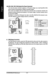
... requirements. It is able to the CPU. If a power supply is used (300W or greater). Align the power connector with its proper location on the motherboard before plugging in the power cord; otherwise, please do not remove it. 42 31 ATX_12V Pin No. 1 2 3 4 Definition GND GND +12V +12V ... system or a system that provides a 24-pin ATX power connector, please remove the small cover on the power connector on the motherboard and connect tightly. Caution! Hardware Installation Please use a power supply that is recommended that a power supply that all the components on the...
... requirements. It is able to the CPU. If a power supply is used (300W or greater). Align the power connector with its proper location on the motherboard before plugging in the power cord; otherwise, please do not remove it. 42 31 ATX_12V Pin No. 1 2 3 4 Definition GND GND +12V +12V ... system or a system that provides a 24-pin ATX power connector, please remove the small cover on the power connector on the motherboard and connect tightly. Caution! Hardware Installation Please use a power supply that is recommended that a power supply that all the components on the...
Manual
Page 22
... designed with color-coded power connector wires. Before attaching the FDD cable, please take note of the foolproof groove in the FDD connector. 34 33 2 1 GA-945GCM(X)-S2 Motherboard - 22 - The black connector wire is used to the FDD drive.
... designed with color-coded power connector wires. Before attaching the FDD cable, please take note of the foolproof groove in the FDD connector. 34 33 2 1 GA-945GCM(X)-S2 Motherboard - 22 - The black connector wire is used to the FDD drive.
Manual
Page 24
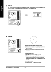
... the positive and negative pins in and turn on /off the computer and unplug the power cord. 2. Turn off . Definition 1 1 MPD+ 2 MPD- 3 MPD- 9) BATTERY GA-945GCM(X)-S2 Motherboard Danger of used batteries according to the manufacturer's instructions. It will blink when the system enters suspend mode(S1). Re-install the battery. 4. Gently take...
... the positive and negative pins in and turn on /off the computer and unplug the power cord. 2. Turn off . Definition 1 1 MPD+ 2 MPD- 3 MPD- 9) BATTERY GA-945GCM(X)-S2 Motherboard Danger of used batteries according to the manufacturer's instructions. It will blink when the system enters suspend mode(S1). Re-install the battery. 4. Gently take...
Manual
Page 26
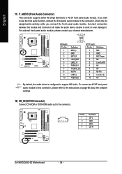
... Pin LINE2_L FSENSE2 1 AC'97 Audio: Pin No. To connect an AC'97 front panel audio module to the connector. Definition 1 CD-L 1 2 GND 3 GND 4 CD-R GA-945GCM(X)-S2 Motherboard - 26 - English 11) F_AUDIO (Front Audio Connector) This connector supports either HD (High Definition) or AC'97 front panel audio module. Pin No.
... Pin LINE2_L FSENSE2 1 AC'97 Audio: Pin No. To connect an AC'97 front panel audio module to the connector. Definition 1 CD-L 1 2 GND 3 GND 4 CD-R GA-945GCM(X)-S2 Motherboard - 26 - English 11) F_AUDIO (Front Audio Connector) This connector supports either HD (High Definition) or AC'97 front panel audio module. Pin No.
Manual
Page 28
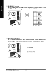
... clear CMOS, temporarily short the two pins. English 15) COMB (COMB Connector) Be careful with the polarity of this header. Open: Normal Short: Clear CMOS GA-945GCM(X)-S2 Motherboard - 28 - Check the pin assignments while you connect the COMB cable.
... clear CMOS, temporarily short the two pins. English 15) COMB (COMB Connector) Be careful with the polarity of this header. Open: Normal Short: Clear CMOS GA-945GCM(X)-S2 Motherboard - 28 - Check the pin assignments while you connect the COMB cable.
Manual
Page 30
English GA-945GCM(X)-S2 Motherboard - 30 -
English GA-945GCM(X)-S2 Motherboard - 30 -


