
User Manual
Page 6
... of Content Warning 4 Chapter 1 Introduction 5 Features Summary 5 GA-8IPE1000 Series Motherboard Layout 8 Block Diagram 9 Chapter 2 Hardware Installation Process 11 Step 1: Install the Central Processing Unit (CPU 12 Step 1-1: CPU Installation 12 Step 1-2 : CPU Cooling Fan Installation 13 Step 2: Install memory modules 14 Step ... Setting Introduction 20 Chapter 3 BIOS Setup 35 The Main Menu (For example: BIOS Ver.: 8IPE1000 Pro-G.E1 36 Standard CMOS Features 38 Advanced BIOS Features 41 Integrated Peripherals 43 Power Management Setup 48 GA-8IPE1000 Series Motherboard - 2 -
... of Content Warning 4 Chapter 1 Introduction 5 Features Summary 5 GA-8IPE1000 Series Motherboard Layout 8 Block Diagram 9 Chapter 2 Hardware Installation Process 11 Step 1: Install the Central Processing Unit (CPU 12 Step 1-1: CPU Installation 12 Step 1-2 : CPU Cooling Fan Installation 13 Step 2: Install memory modules 14 Step ... Setting Introduction 20 Chapter 3 BIOS Setup 35 The Main Menu (For example: BIOS Ver.: 8IPE1000 Pro-G.E1 36 Standard CMOS Features 38 Advanced BIOS Features 41 Integrated Peripherals 43 Power Management Setup 48 GA-8IPE1000 Series Motherboard - 2 -

User Manual
Page 9
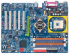
... size form factor, 4 layers PCB. - English Chapter 1 Introduction Features Summary Form Factor Motherboard CPU Chip set Memory I /O Controller Hub - 4 184-pin DDR DIMM sockets - GA-8IPE1000 Series Motherboard: GA-8IPE1000 Pro-G/GA-8IPE1000-G/GA-8IPE1000 - Intel Pentium®4 400/533/800MHz FSB - 2nd cache depends on CPU - Chipset Intel 865PE HOST/AGP/Controller - Supports up to be continued...... Supports PIO mode3...
... size form factor, 4 layers PCB. - English Chapter 1 Introduction Features Summary Form Factor Motherboard CPU Chip set Memory I /O Controller Hub - 4 184-pin DDR DIMM sockets - GA-8IPE1000 Series Motherboard: GA-8IPE1000 Pro-G/GA-8IPE1000-G/GA-8IPE1000 - Intel Pentium®4 400/533/800MHz FSB - 2nd cache depends on CPU - Chipset Intel 865PE HOST/AGP/Controller - Supports up to be continued...... Supports PIO mode3...

User Manual
Page 10
... In - CD_In / Game Connector - PS/2 Keyboard interface and PS/2 Mouse interface - Supports Face Wizard (*) to be continued...... (*) For GA-8IPE1000 Pro-G only. (u) For GA-8IPE1000-G only. CPU/Power (*)/System Fan Revolution detect - CPU Overheat Warning - Realtek ALC850 UAJ CODEC - Licensed AWARD BIOS - B o a r d L A N ( u) * O n - Ti TSB43AB23 - GA-8IPE1000 Series Motherboard - 6 - Build in Marvell 8001 Chipset (10/100/1000 Mbit)(*u) - 1 RJ45 port...
... In - CD_In / Game Connector - PS/2 Keyboard interface and PS/2 Mouse interface - Supports Face Wizard (*) to be continued...... (*) For GA-8IPE1000 Pro-G only. (u) For GA-8IPE1000-G only. CPU/Power (*)/System Fan Revolution detect - CPU Overheat Warning - Realtek ALC850 UAJ CODEC - Licensed AWARD BIOS - B o a r d L A N ( u) * O n - Ti TSB43AB23 - GA-8IPE1000 Series Motherboard - 6 - Build in Marvell 8001 Chipset (10/100/1000 Mbit)(*u) - 1 RJ45 port...

User Manual
Page 11
... Technology and has it enabled - Whether your hardware configurations, including CPU, Chipsets, Memory, Cards... .etc. (*) For GA-8IPE1000 Pro-G only. - 7 - STR(Suspend-To-RAM) - Supports CPU Smart Fan Control function (*) - PS/2 Keyboard power on - USB KB/Mouse wake up from S3 - Over Voltage (DDR/AGP/CPU) by BIOS HT functionality requirement content : Enabling the functionality of...
... Technology and has it enabled - Whether your hardware configurations, including CPU, Chipsets, Memory, Cards... .etc. (*) For GA-8IPE1000 Pro-G only. - 7 - STR(Suspend-To-RAM) - Supports CPU Smart Fan Control function (*) - PS/2 Keyboard power on - USB KB/Mouse wake up from S3 - Over Voltage (DDR/AGP/CPU) by BIOS HT functionality requirement content : Enabling the functionality of...

User Manual
Page 13
English Block Diagram AGP 8X/4X Pentium 4 Socket 478 CPU CPUCLK+/- (100/133/200MHz) AGPCLK (66M Hz) 5 PCI System Bus 400/533/800MHz DDR 266/333/400MHz Intel 865PE ZCLK (66MHz) IEEE 1394 (*) RJ45 (*u) T SB43AB23(*) ...) USBCLK (48MHz) 14.318 M Hz 33 M Hz 24 M Hz CLK GEN ZCLK (66MHz) CPUCLK+/- (100/133/200MHz) AGPCLK (66MHz) HCLK+/- (100/133MHz) ICH3V66 (66MHz) (*) For GA-8IPE1000 Pro-G only. (u) For GA-8IPE1000-G only. - 9 - Hardware Installation Process
English Block Diagram AGP 8X/4X Pentium 4 Socket 478 CPU CPUCLK+/- (100/133/200MHz) AGPCLK (66M Hz) 5 PCI System Bus 400/533/800MHz DDR 266/333/400MHz Intel 865PE ZCLK (66MHz) IEEE 1394 (*) RJ45 (*u) T SB43AB23(*) ...) USBCLK (48MHz) 14.318 M Hz 33 M Hz 24 M Hz CLK GEN ZCLK (66MHz) CPUCLK+/- (100/133/200MHz) AGPCLK (66MHz) HCLK+/- (100/133MHz) ICH3V66 (66MHz) (*) For GA-8IPE1000 Pro-G only. (u) For GA-8IPE1000-G only. - 9 - Hardware Installation Process

User Manual
Page 15
Install the Central Processing Unit (CPU) Step 2- Note: If the NorthBridge on the power supply or connect the power cable to the power outlet. Install memory modules Step 3- Install expansion cards ...
Install the Central Processing Unit (CPU) Step 2- Note: If the NorthBridge on the power supply or connect the power cable to the power outlet. Install memory modules Step 3- Install expansion cards ...

User Manual
Page 16
...Socket Actuation Lever 1. English Step 1: Install the Central Processing Unit (CPU) Before installing the processor,adhere to the following warning: If you do not match the CPU socket Pin 1 and CPU cut edge on the CPU upper corner. Locate Pin 1 in the socketand look for a (...golden) cut edge well, it will cause improper installation. Then insert the CPU into the socket. - 12 - Step 1-1: CPU Installation Angling the ro d to 90-degree when a noise "cough" made. 2. CPU Top View GA-8IPE1000 Series Motherboard 4. Please change the insert orientation. Pullthe rod to the 90-degree...
...Socket Actuation Lever 1. English Step 1: Install the Central Processing Unit (CPU) Before installing the processor,adhere to the following warning: If you do not match the CPU socket Pin 1 and CPU cut edge on the CPU upper corner. Locate Pin 1 in the socketand look for a (...golden) cut edge well, it will cause improper installation. Then insert the CPU into the socket. - 12 - Step 1-1: CPU Installation Angling the ro d to 90-degree when a noise "cough" made. 2. CPU Top View GA-8IPE1000 Series Motherboard 4. Please change the insert orientation. Pullthe rod to the 90-degree...

User Manual
Page 17
...ofthe CPUsocket alone with extreme caution.) 3. We recommend you to apply the thermal tape to provide better heatconduction between your CPU and cooling fan. (The CPU cooling fan might stick to the CPUdue to the hardening of the thermal paste.During this condition if you try to remove... plugged to CPUcooling fanuser's manualfor more detailinstallation procedure. 1. Hardware Installation Process To avoid this completes the installation. Make sure the CPU fan is plugged in to the CPU fan connector, this from happening,we suggestyou to the following warning: 1. Please refer to the...
...ofthe CPUsocket alone with extreme caution.) 3. We recommend you to apply the thermal tape to provide better heatconduction between your CPU and cooling fan. (The CPU cooling fan might stick to the CPUdue to the hardening of the thermal paste.During this condition if you try to remove... plugged to CPUcooling fanuser's manualfor more detailinstallation procedure. 1. Hardware Installation Process To avoid this completes the installation. Make sure the CPU fan is plugged in to the CPU fan connector, this from happening,we suggestyou to the following warning: 1. Please refer to the...

User Manual
Page 25
... supply unit after ATX power cable and other related devices are firmly connected to the mainboard. English 1) ATX_12V (+12VPower Connector) This connector (ATX _12V) suppliesthe CPU operation voltage (Vcore). If this " ATX_ 12V connector" is not connected, system cannotboot. PinNo. Pin No. Definition 1 3.3V 2 3.3V 3 GND 4 VCC 11 1 5 GND 6 VCC 7 GND...
... supply unit after ATX power cable and other related devices are firmly connected to the mainboard. English 1) ATX_12V (+12VPower Connector) This connector (ATX _12V) suppliesthe CPU operation voltage (Vcore). If this " ATX_ 12V connector" is not connected, system cannotboot. PinNo. Pin No. Definition 1 3.3V 2 3.3V 3 GND 4 VCC 11 1 5 GND 6 VCC 7 GND...

User Manual
Page 26
Definition 1 GND 1 2 +12V 3 Sense GA-8IPE1000 Series Motherboard - 22 - current up to lower the system temperature. Definition 1 GND 1 2 +12V 3 Sense 4) SYS_FAN (System FAN Connector) This connector allows you to link with the cooling fan on the system case to 600 mA. PinNo. PinNo. English 3) CPU_FAN (CPU FAN Connector) Please note, a proper installation of the CPU cooler is essential to prevent the CPU from running under abnormal condition or damaged by overheating.The CPU fan connector supports Max.
Definition 1 GND 1 2 +12V 3 Sense GA-8IPE1000 Series Motherboard - 22 - current up to lower the system temperature. Definition 1 GND 1 2 +12V 3 Sense 4) SYS_FAN (System FAN Connector) This connector allows you to link with the cooling fan on the system case to 600 mA. PinNo. PinNo. English 3) CPU_FAN (CPU FAN Connector) Please note, a proper installation of the CPU cooler is essential to prevent the CPU from running under abnormal condition or damaged by overheating.The CPU fan connector supports Max.

User Manual
Page 41
BIOS Setup l Power Manag ement Setup This setup page includes all CMOS value changes and exit setup. (*) For GA-8IPE1000 Pro-G only. - 37 - l Set Supervis or password Change, set , or disable password. l Exit Without Saving Abandon all the items of Green function features. ...allows you to limit access to the system and Setup, or just to CMOS and exit setup. l Frequency/Voltage Control This setup page is control CPU's clock and frequency ratio. l Set User password Change, set , or disable password. l Load Optimized Defaults Optimized Defaults indicates the value of ...
BIOS Setup l Power Manag ement Setup This setup page includes all CMOS value changes and exit setup. (*) For GA-8IPE1000 Pro-G only. - 37 - l Set Supervis or password Change, set , or disable password. l Exit Without Saving Abandon all the items of Green function features. ...allows you to limit access to the system and Setup, or just to CMOS and exit setup. l Frequency/Voltage Control This setup page is control CPU's clock and frequency ratio. l Set User password Change, set , or disable password. l Load Optimized Defaults Optimized Defaults indicates the value of ...

User Manual
Page 44
... The category determines whether the computer will determine the amount of memory located above 1 MB in the system. GA-8IPE1000 Series Motherboard - 40 - This is the amount of base (or conventional) memory installed in the CPU's memory address map. it w ill stop for all other errors. (Default v alue) All, But Diskette The sy...
... The category determines whether the computer will determine the amount of memory located above 1 MB in the system. GA-8IPE1000 Series Motherboard - 40 - This is the amount of base (or conventional) memory installed in the CPU's memory address map. it w ill stop for all other errors. (Default v alue) All, But Diskette The sy...

User Manual
Page 45
USB-ZIP Select y our boot dev ice priority by ZIP. ZIP Select y our boot dev ice priority by USB-ZIP. (*) For GA-8IPE1000 Pro-G only. - 41 - LS120 Select y our boot dev ice priority by Floppy . Floppy Select y our boot dev ice priority by LS120. USB-FDD Select... [Press Enter] Item Help First Boot Dev ice [Floppy ] MenuLevelu Second Boot Dev ice [Hard Disk] Third Boot Dev ice [CDROM] Passw ord Check [Setup] # CPU Hy per-Threading [Enabled] higf: Mov e Enter:Select +/-/PU/PD:Value F10:Sav e ESC:Ex it F1:General Help * F 3 : L a n g u a g e ( ) F5:Prev ...
USB-ZIP Select y our boot dev ice priority by ZIP. ZIP Select y our boot dev ice priority by USB-ZIP. (*) For GA-8IPE1000 Pro-G only. - 41 - LS120 Select y our boot dev ice priority by Floppy . Floppy Select y our boot dev ice priority by LS120. USB-FDD Select... [Press Enter] Item Help First Boot Dev ice [Floppy ] MenuLevelu Second Boot Dev ice [Hard Disk] Third Boot Dev ice [CDROM] Passw ord Check [Setup] # CPU Hy per-Threading [Enabled] higf: Mov e Enter:Select +/-/PU/PD:Value F10:Sav e ESC:Ex it F1:General Help * F 3 : L a n g u a g e ( ) F5:Prev ...

User Manual
Page 46
... page if the correct passw ord is only w orking for operating sy stem w ith multi processors mode supported. (Default v alue) Disabled Disables CPU Hy per Threading Feature. Select y our boot dev ice priority by LAN. Setup The sy stem w ill boot but w ill not access to... Setup page if the correct passw ord is not entered at the prompt. (Default v alue) CPU Hyper-Threading Enabled Enables CPU Hy per Threading. Select y our boot dev ice priority by Disabled. GA-8IPE1000 Series Motherboard - 42 - Please note that this feature is not entered at the prompt. English ...
... page if the correct passw ord is only w orking for operating sy stem w ith multi processors mode supported. (Default v alue) Disabled Disables CPU Hy per Threading Feature. Select y our boot dev ice priority by LAN. Setup The sy stem w ill boot but w ill not access to... Setup page if the correct passw ord is not entered at the prompt. (Default v alue) CPU Hyper-Threading Enabled Enables CPU Hy per Threading. Select y our boot dev ice priority by Disabled. GA-8IPE1000 Series Motherboard - 42 - Please note that this feature is not entered at the prompt. English ...

User Manual
Page 55
... Don't reset case +3.3V OK open status +5V OK +12V OK [Enabled] Current CPU Temperature 40°C Clear case open Current CPU FAN Speed 6490 RPM status at nex t boot * C u r r e n t P O W E R F A N S p e e d ( ) 0 RPM Current SYSTEM FAN Speed 0 RPM CPU Warning Temperature [Disabled] CPU FAN Fail Warning [Disabled] * P O W E R F A N F a i l W a r i n g ( )... Case Open Status" to "Enabled" and sav e CMOS, y our computer w ill res tart. automatically. (*) For GA-8IPE1000 Pro-G only. - 51 - Current Voltage (V) Vcore / DDR25V / +3.3V / +5V / +12V Detect sy stem's ...
... Don't reset case +3.3V OK open status +5V OK +12V OK [Enabled] Current CPU Temperature 40°C Clear case open Current CPU FAN Speed 6490 RPM status at nex t boot * C u r r e n t P O W E R F A N S p e e d ( ) 0 RPM Current SYSTEM FAN Speed 0 RPM CPU Warning Temperature [Disabled] CPU FAN Fail Warning [Disabled] * P O W E R F A N F a i l W a r i n g ( )... Case Open Status" to "Enabled" and sav e CMOS, y our computer w ill res tart. automatically. (*) For GA-8IPE1000 Pro-G only. - 51 - Current Voltage (V) Vcore / DDR25V / +3.3V / +5V / +12V Detect sy stem's ...

User Manual
Page 56
... Disabled Fan Warning Function Disable. (Default v alue) Enabled Fan Warning Function Enable. When the CPU temperature is higher than 40 degrees Celsius, CPU fan w ill run at low speed. (*) For GA-8IPE1000 Pro-G only. English Current CPU/POWER (*)/SYSTEM FAN Speed (RPM) Detect CPU/POWER (*)/SYSTEM Fan speed status automatically . at 70°C / 158°F. 80°...
... Disabled Fan Warning Function Disable. (Default v alue) Enabled Fan Warning Function Enable. When the CPU temperature is higher than 40 degrees Celsius, CPU fan w ill run at low speed. (*) For GA-8IPE1000 Pro-G only. English Current CPU/POWER (*)/SYSTEM FAN Speed (RPM) Detect CPU/POWER (*)/SYSTEM Fan speed status automatically . at 70°C / 158°F. 80°...

User Manual
Page 57
... [Auto] Memory Frequency (Mhz) 266 AGP/PCI/SRC Frequency (Mhz) 66/33/100 AGP Ov erVoltage Control [Normal] DIMM Ov erVoltage Control [Normal] CPU Voltage Control [Normal] Normal CPU Vcore 1.4750V higf: Mov e Enter:Select +/-/PU/PD:Value F10:Sav e ESC:Ex it F1:General Help * F 3 : L a n g u ...: 16X The option w ill display "Locked" and read only if the CPU ratio is set to Enabled. This setup option will be available when "CPU Host Clock Control" is not changeable. (*) For GA-8IPE1000 Pro-G only. - 53 - BIOS Setup English Frequency/Voltage Control CMOS Setup Utility...
... [Auto] Memory Frequency (Mhz) 266 AGP/PCI/SRC Frequency (Mhz) 66/33/100 AGP Ov erVoltage Control [Normal] DIMM Ov erVoltage Control [Normal] CPU Voltage Control [Normal] Normal CPU Vcore 1.4750V higf: Mov e Enter:Select +/-/PU/PD:Value F10:Sav e ESC:Ex it F1:General Help * F 3 : L a n g u ...: 16X The option w ill display "Locked" and read only if the CPU ratio is set to Enabled. This setup option will be available when "CPU Host Clock Control" is not changeable. (*) For GA-8IPE1000 Pro-G only. - 53 - BIOS Setup English Frequency/Voltage Control CMOS Setup Utility...

User Manual
Page 58
... 1.33. For pow er End-User use FSB800 Pentium 4 processor, please set "CPU Clock" to 355MHz. Memory Frequency For for times out reboot. Auto Set Memory frequency by DRAM SPD data. (Default v alue) GA-8IPE1000 Series Motherboard - 54 - SRC ov er clock may cause y our sy stem ...broken. Adjust AGP/PCI/SRC clock asy chrohous w ith CPU. Disabled Disable CPU Host Clock Control.(Default v alue) Enabled Enable CPU Host Clock Control.
... 1.33. For pow er End-User use FSB800 Pentium 4 processor, please set "CPU Clock" to 355MHz. Memory Frequency For for times out reboot. Auto Set Memory frequency by DRAM SPD data. (Default v alue) GA-8IPE1000 Series Motherboard - 54 - SRC ov er clock may cause y our sy stem ...broken. Adjust AGP/PCI/SRC clock asy chrohous w ith CPU. Disabled Disable CPU Host Clock Control.(Default v alue) Enabled Enable CPU Host Clock Control.

User Manual
Page 59
.... +0.2V Set AGP Ov erVoltage Control to +0.2V. +0.3V Set AGP Ov erVoltage Control to 1.7600V. (Default v alue: Normal) Normal CPU Vcore Display y our CPU Vcore Voltage. - 55 - English Memory Frequency(Mhz) The v alues depend on Fix ed AGP/PCI/SRC Frequency . AGP/PCI/SRC Frequency(...Mhz) The v alues depend on CPU Host Frequency (Mhz). BIOS Setup CPU Voltag e Control Supports adjustable CPU Vcore from 0.8375V to +0.3V. DIMM OverVol tage Control Normal Set DIMM Ov erVoltage Control to Normal. (Default v...
.... +0.2V Set AGP Ov erVoltage Control to +0.2V. +0.3V Set AGP Ov erVoltage Control to 1.7600V. (Default v alue: Normal) Normal CPU Vcore Display y our CPU Vcore Voltage. - 55 - English Memory Frequency(Mhz) The v alues depend on Fix ed AGP/PCI/SRC Frequency . AGP/PCI/SRC Frequency(...Mhz) The v alues depend on CPU Host Frequency (Mhz). BIOS Setup CPU Voltag e Control Supports adjustable CPU Vcore from 0.8375V to +0.3V. DIMM OverVol tage Control Normal Set DIMM Ov erVoltage Control to Normal. (Default v...
User Manual
Page 68
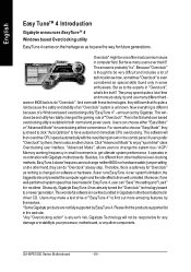
... utilityhas totally changed on software or hardware. GA-8IPE1000 Series Motherboard - 64 - Overclock" mightbe oneofthe mostcommon issues in coordination with these technologies, they justneed to click "Auto Optimize" to have many users ever tried it is unknown. But have autoed and immediate CPU overclocking. And even with Gigabyte motherboards. Therefore, this setting and "Load...
... utilityhas totally changed on software or hardware. GA-8IPE1000 Series Motherboard - 64 - Overclock" mightbe oneofthe mostcommon issues in coordination with these technologies, they justneed to click "Auto Optimize" to have many users ever tried it is unknown. But have autoed and immediate CPU overclocking. And even with Gigabyte motherboards. Therefore, this setting and "Load...


