
Manual
Page 1
GA-8I945PLGE-RH Intel® Pentium® D / Pentium® 4 LGA775 Processor Motherboard User's Manual Rev. 1001 12ME-945PLGER-1001R * The WEEE marking on the product indicates this product must not be disposed of with user's other household waste and must be handed over to a designated collection point for the recycling of waste electrical and electronic equipment!! * The WEEE marking applies only in European Union's member states.
GA-8I945PLGE-RH Intel® Pentium® D / Pentium® 4 LGA775 Processor Motherboard User's Manual Rev. 1001 12ME-945PLGER-1001R * The WEEE marking on the product indicates this product must not be disposed of with user's other household waste and must be handed over to a designated collection point for the recycling of waste electrical and electronic equipment!! * The WEEE marking applies only in European Union's member states.

Manual
Page 2
Motherboard GA-8I945PLGE-RH Jan. 11, 2006 Motherboard GA-8I945PLGE-RH Jan. 11, 2006
Motherboard GA-8I945PLGE-RH Jan. 11, 2006 Motherboard GA-8I945PLGE-RH Jan. 11, 2006

Manual
Page 4
Table of Contents GA-8I945PLGE-RH Motherboard Layout 6 Block Diagram ...7 Chapter 1 Hardware Installation 9 1-1 Considerations Prior to Installation 9 1-2 Feature Summary 10 1-3 Installation of the CPU and Heatsink 12 1-3-1 Installation of the CPU ...
Table of Contents GA-8I945PLGE-RH Motherboard Layout 6 Block Diagram ...7 Chapter 1 Hardware Installation 9 1-1 Considerations Prior to Installation 9 1-2 Feature Summary 10 1-3 Installation of the CPU and Heatsink 12 1-3-1 Installation of the CPU ...

Manual
Page 6
GA-8I945PLGE-RH Motherboard Layout KB_MS COAXIAL OPTICAL ATX_12V LGA775 CPU_FAN LPT GA-8I945PLGE-RH VGA_COM USB LAN USB AUDIO1 AUDIO2 F_AUDIO RTL 8111B SYS_FAN PCIE_16 Intel 945PL PCIE_1 CD_IN PCIE_2 CODEC PCI1 PCI2 IT8712 PCI3 CI FDD SPDIF_I RF_ID CLR_CMOS IDE1 BAT ICH7 BIOS SATAII2 SATAII3 SATAII0 SATAII1 F_USB1 F_USB2 DDRII1 DDRII2 ATX PWR_LED F_PANEL - 6 -
GA-8I945PLGE-RH Motherboard Layout KB_MS COAXIAL OPTICAL ATX_12V LGA775 CPU_FAN LPT GA-8I945PLGE-RH VGA_COM USB LAN USB AUDIO1 AUDIO2 F_AUDIO RTL 8111B SYS_FAN PCIE_16 Intel 945PL PCIE_1 CD_IN PCIE_2 CODEC PCI1 PCI2 IT8712 PCI3 CI FDD SPDIF_I RF_ID CLR_CMOS IDE1 BAT ICH7 BIOS SATAII2 SATAII3 SATAII0 SATAII1 F_USB1 F_USB2 DDRII1 DDRII2 ATX PWR_LED F_PANEL - 6 -

Manual
Page 10
... Š 4 USB 2.0/1.1 ports Š 6 audio jacks (Line In / Line Out / MIC In/Surround Speaker Out (Rear Speaker Out)/Center/Subwoofer Speaker Out/Side Speaker Out) GA-8I945PLGE-RH Motherboard - 10 -
... Š 4 USB 2.0/1.1 ports Š 6 audio jacks (Line In / Line Out / MIC In/Surround Speaker Out (Rear Speaker Out)/Center/Subwoofer Speaker Out/Side Speaker Out) GA-8I945PLGE-RH Motherboard - 10 -
Manual
Page 12
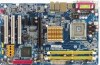
... socket. OS: An operation system that the system bus frequency be set beyond the proper specifications, please do so according to the CPU during installation.) GA-8I945PLGE-RH Motherboard - 12 - Align the indented corner of the CPU Metal Lever Fig. 1 Gently lift the metal lever located on the edge of the following conditions...
... socket. OS: An operation system that the system bus frequency be set beyond the proper specifications, please do so according to the CPU during installation.) GA-8I945PLGE-RH Motherboard - 12 - Align the indented corner of the CPU Metal Lever Fig. 1 Gently lift the metal lever located on the edge of the following conditions...

Manual
Page 14
... can be installed in one direction. If you wish to remove the DIMM module. English 1-4 Installation of the DIMM sockets to lock the DIMM module. GA-8I945PLGE-RH Motherboard - 14 - Please make sure that they can differ with the following conditions: 1.
... can be installed in one direction. If you wish to remove the DIMM module. English 1-4 Installation of the DIMM sockets to lock the DIMM module. GA-8I945PLGE-RH Motherboard - 14 - Please make sure that they can differ with the following conditions: 1.
Manual
Page 15
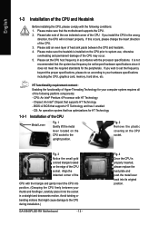
... mode will add double. To enable Dual Channel mode, please insert two DDR II memory modules (it is installed. 2. English Dual Channel Memory Configuration The GA-8I945PLGE-RH supports the Dual Channel Technology. After operating the Dual Channel Technology, the bandwidth of Memory Bus will not be enabled if only one DDR II... memory module is recommended to the limitation of identical brand, size, chips, and speed) into DDRII1 and DDRII2 memory sockets. - 15 - Hardware Installation The GA-8I945PLGE-RH includes 2 DIMM sockets.
... mode will add double. To enable Dual Channel mode, please insert two DDR II memory modules (it is installed. 2. English Dual Channel Memory Configuration The GA-8I945PLGE-RH supports the Dual Channel Technology. After operating the Dual Channel Technology, the bandwidth of Memory Bus will not be enabled if only one DDR II... memory module is recommended to the limitation of identical brand, size, chips, and speed) into DDRII1 and DDRII2 memory sockets. - 15 - Hardware Installation The GA-8I945PLGE-RH includes 2 DIMM sockets.
Manual
Page 16
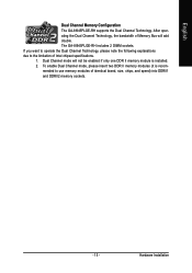
... document before install the expansion card into expansion slot in the slot. 5. Make sure your VGA card is locked by following the steps outlined below: 1. GA-8I945PLGE-RH Motherboard - 16 - Installing a PCI Express x 16 expansion card: Please align the VGA card to the onboard PCI Express x 16 slot and press firmly down on...
... document before install the expansion card into expansion slot in the slot. 5. Make sure your VGA card is locked by following the steps outlined below: 1. GA-8I945PLGE-RH Motherboard - 16 - Installing a PCI Express x 16 expansion card: Please align the VGA card to the onboard PCI Express x 16 slot and press firmly down on...
Manual
Page 18
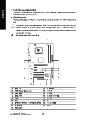
...) 11) CD_IN 3) CPU_FAN 12) SPDIF_I 4) SYS_FAN 13) F_USB1/F_USB2 5) FDD 14) RF_ID 6) IDE1 15) CI 7) SATAII0 / SATAII1 / SATAII2 / SATAII3 16) CLR_CMOS 8) F_AUDIO 17) BAT 9) PWR_LED GA-8I945PLGE-RH Motherboard - 18 - Surround side speakers can be connected to perform different functions via the audio software. Please refer to the 2-/4-/6-/8- Side Speaker Out The default...
...) 11) CD_IN 3) CPU_FAN 12) SPDIF_I 4) SYS_FAN 13) F_USB1/F_USB2 5) FDD 14) RF_ID 6) IDE1 15) CI 7) SATAII0 / SATAII1 / SATAII2 / SATAII3 16) CLR_CMOS 8) F_AUDIO 17) BAT 9) PWR_LED GA-8I945PLGE-RH Motherboard - 18 - Surround side speakers can be connected to perform different functions via the audio software. Please refer to the 2-/4-/6-/8- Side Speaker Out The default...
Manual
Page 20
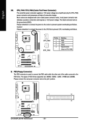
... the power to the CPU fan to the FDD drive. Please remember to connect the power to the cooler to the pin1 position. 2 34 1 33 GA-8I945PLGE-RH Motherboard - 20 - English 3/4) CPU_FAN / SYS_FAN (Cooler Fan Power Connector) The cooler fan power connector supplies a +12V power voltage via a 3-pin/4-pin (only for CPU_FAN) 5) FDD...
... the power to the CPU fan to the FDD drive. Please remember to connect the power to the cooler to the pin1 position. 2 34 1 33 GA-8I945PLGE-RH Motherboard - 20 - English 3/4) CPU_FAN / SYS_FAN (Cooler Fan Power Connector) The cooler fan power connector supplies a +12V power voltage via a 3-pin/4-pin (only for CPU_FAN) 5) FDD...

Manual
Page 22
... No. Check the pin assignments carefully while you wish to use the front audio function, connect the front panel audio module to support HD Audio. GA-8I945PLGE-RH Motherboard - 22 - Incorrect connection between the module and connector will blink when the system enters suspend mode. To connect an AC97 front panel audio module...
... No. Check the pin assignments carefully while you wish to use the front audio function, connect the front panel audio module to support HD Audio. GA-8I945PLGE-RH Motherboard - 22 - Incorrect connection between the module and connector will blink when the system enters suspend mode. To connect an AC97 front panel audio module...
Manual
Page 24
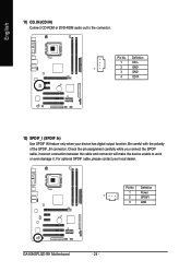
Pin No. Definition 1 Power 1 2 SPDIFI 3 GND GA-8I945PLGE-RH Motherboard - 24 - Check the pin assignment carefully while you connect the SPDIF cable, incorrect connection between the cable and connector will make the device unable ...
Pin No. Definition 1 Power 1 2 SPDIFI 3 GND GA-8I945PLGE-RH Motherboard - 24 - Check the pin assignment carefully while you connect the SPDIF cable, incorrect connection between the cable and connector will make the device unable ...

Manual
Page 26
To clear CMOS, temporarily short 1-2 pin. Definition 1 1 Signal 2 GND 16) CLR_CMOS (Clear CMOS) You may clear the CMOS data to its default values by this jumper. 1 Open: Normal 1 Short: Clear CMOS GA-8I945PLGE-RH Motherboard - 26 - Default doesn't include the "Shunter" to detect if the chassis cover is removed. English 15) CI (Chassis Intrusion, Case Open) This 2-pin connector allows your system to prevent from improper use this jumper. You can check the "Case Opened" status in BIOS Setup. Pin No.
To clear CMOS, temporarily short 1-2 pin. Definition 1 1 Signal 2 GND 16) CLR_CMOS (Clear CMOS) You may clear the CMOS data to its default values by this jumper. 1 Open: Normal 1 Short: Clear CMOS GA-8I945PLGE-RH Motherboard - 26 - Default doesn't include the "Shunter" to detect if the chassis cover is removed. English 15) CI (Chassis Intrusion, Case Open) This 2-pin connector allows your system to prevent from improper use this jumper. You can check the "Case Opened" status in BIOS Setup. Pin No.

Manual
Page 30
... Load Optimized Defaults in the BIOS when somehow the system works not stable as figure below) will appear on cards) device. Intel I945 BIOS for 8I945PLGE-RH E6 . . . . :BIOS Setup/Q-Flash, : Xpress Recovery2, For Boot Menu 11/07/2005-I945-6A79HG0GC-00 For Boot Menu Use < > or < > to ...:Exit The Main Menu (For example: BIOS Ver. : F1a) Once you want, please press "Ctrl+F1" to search the advanced option hidden. GA-8I945PLGE-RH Motherboard - 30 - English : For Boot Menu Select boot sequence for stability. Press to accept or enter the sub-menu. Use arrow keys to ...
... Load Optimized Defaults in the BIOS when somehow the system works not stable as figure below) will appear on cards) device. Intel I945 BIOS for 8I945PLGE-RH E6 . . . . :BIOS Setup/Q-Flash, : Xpress Recovery2, For Boot Menu 11/07/2005-I945-6A79HG0GC-00 For Boot Menu Use < > or < > to ...:Exit The Main Menu (For example: BIOS Ver. : F1a) Once you want, please press "Ctrl+F1" to search the advanced option hidden. GA-8I945PLGE-RH Motherboard - 30 - English : For Boot Menu Select boot sequence for stability. Press to accept or enter the sub-menu. Use arrow keys to ...

Manual
Page 32
... "Enter" to set the access mode for faster system start up . is display only The month, Jan. The four options are : Large/Auto(default:Auto) GA-8I945PLGE-RH Motherboard - 32 - English 2-1 Standard CMOS Features Date (mm:dd:yy) Time (hh:mm:ss) CMOS Setup Utility-Copyright (C) 1984-2005 Award Software Standard CMOS Features...
... "Enter" to set the access mode for faster system start up . is display only The month, Jan. The four options are : Large/Auto(default:Auto) GA-8I945PLGE-RH Motherboard - 32 - English 2-1 Standard CMOS Features Date (mm:dd:yy) Time (hh:mm:ss) CMOS Setup Utility-Copyright (C) 1984-2005 Award Software Standard CMOS Features...

Manual
Page 34
... not boot and will show up when you install a processor which supports this menu. ZIP USB-FDD Select your boot device priority by USB-FDD. GA-8I945PLGE-RH Motherboard - 34 - Select your boot device priority by LAN. USB-ZIP Select your boot device priority by ZIP. Select your boot device priority by CDROM...
... not boot and will show up when you install a processor which supports this menu. ZIP USB-FDD Select your boot device priority by USB-FDD. GA-8I945PLGE-RH Motherboard - 34 - Select your boot device priority by LAN. USB-ZIP Select your boot device priority by ZIP. Select your boot device priority by CDROM...

Manual
Page 36
PATA devices will be simulated to ". GA-8I945PLGE-RH Motherboard - 36 - Enhanced Set On-Chip SATA mode to Enhanced, the motherboard allows up to 4 HDDs on the motherboard; 2 for SATA and the other for ...
PATA devices will be simulated to ". GA-8I945PLGE-RH Motherboard - 36 - Enhanced Set On-Chip SATA mode to Enhanced, the motherboard allows up to 4 HDDs on the motherboard; 2 for SATA and the other for ...

Manual
Page 38
... PME Event Wake Up Power On by Ring Resume by PWR-BTTN Instant-Off Delay 4 Sec. Enabled Enable Power on by Ring function. (Default value) GA-8I945PLGE-RH Motherboard - 38 - Enter suspend if button is pressed less than 4 sec. Soft-Off by Alarm x Date (of Month) Alarm x Time (hh:mm:ss) Alarm Power...
... PME Event Wake Up Power On by Ring Resume by PWR-BTTN Instant-Off Delay 4 Sec. Enabled Enable Power on by Ring function. (Default value) GA-8I945PLGE-RH Motherboard - 38 - Enter suspend if button is pressed less than 4 sec. Soft-Off by Alarm x Date (of Month) Alarm x Time (hh:mm:ss) Alarm Power...

Manual
Page 40
GA-8I945PLGE-RH Motherboard - 40 - Auto assign IRQ to PCI 3. (Default value) Set IRQ 3,4,5,7,9,10,11,12,14,15 to PCI 2. Auto assign IRQ to PCI 2. (Default value) ...
GA-8I945PLGE-RH Motherboard - 40 - Auto assign IRQ to PCI 3. (Default value) Set IRQ 3,4,5,7,9,10,11,12,14,15 to PCI 2. Auto assign IRQ to PCI 2. (Default value) ...


