Manual
Page 1
GA-8I945P Pro/ GA-8I945P-G Intel® Pentium® D / Pentium® 4 LGA775 Processor Motherboard User's Manual Rev. 1005 12ME-8I945PP-1005 * The WEEE marking on the product indicates this product must not be disposed of with user's other household waste and must be handed over to a designated collection point for the recycling of waste electrical and electronic equipment!! * The WEEE marking applies only in European Union's member states.
GA-8I945P Pro/ GA-8I945P-G Intel® Pentium® D / Pentium® 4 LGA775 Processor Motherboard User's Manual Rev. 1005 12ME-8I945PP-1005 * The WEEE marking on the product indicates this product must not be disposed of with user's other household waste and must be handed over to a designated collection point for the recycling of waste electrical and electronic equipment!! * The WEEE marking applies only in European Union's member states.
Manual
Page 2
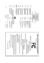
Motherboard GA-8I945P Pro/GA-8I945P-G Apr. 18, 2005 Motherboard GA-8I945P Pro/GA-8I945P-G Apr. 18, 2005
Motherboard GA-8I945P Pro/GA-8I945P-G Apr. 18, 2005 Motherboard GA-8I945P Pro/GA-8I945P-G Apr. 18, 2005
Manual
Page 4
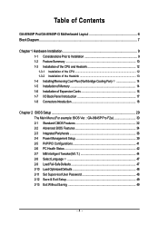
Table of Contents GA-8I945P Pro/GA-8I945P-G Motherboard Layout 6 Block Diagram ...7 Chapter 1 Hardware Installation 9 1-1 Considerations Prior to Installation 9 1-2 Feature Summary 10 1-3 Installation of the CPU and Heatsink ...Installation of Expansion Cards 16 1-7 I/O Back Panel Introduction 17 1-8 Connectors Introduction 18 Chapter 2 BIOS Setup 29 The Main Menu (For example: BIOS Ver. : GA-8I945P Pro F2a 30 2-1 Standard CMOS Features 32 2-2 Advanced BIOS Features 34 2-3 IntegratedPeripherals 36 2-4 Power Management Setup 39 2-5 PnP/PCI Configurations 41 2-6 PC Health Status 42...
Table of Contents GA-8I945P Pro/GA-8I945P-G Motherboard Layout 6 Block Diagram ...7 Chapter 1 Hardware Installation 9 1-1 Considerations Prior to Installation 9 1-2 Feature Summary 10 1-3 Installation of the CPU and Heatsink ...Installation of Expansion Cards 16 1-7 I/O Back Panel Introduction 17 1-8 Connectors Introduction 18 Chapter 2 BIOS Setup 29 The Main Menu (For example: BIOS Ver. : GA-8I945P Pro F2a 30 2-1 Standard CMOS Features 32 2-2 Advanced BIOS Features 34 2-3 IntegratedPeripherals 36 2-4 Power Management Setup 39 2-5 PnP/PCI Configurations 41 2-6 PC Health Status 42...
Manual
Page 5
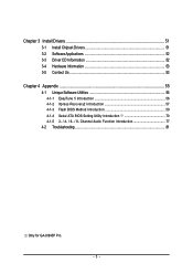
Chapter 3 Install Drivers 51 3-1 Install Chipset Drivers 51 3-2 SoftwareApplications 52 3-3 Driver CD Information 52 3-4 Hardware Information 53 3-5 Contact Us ...53 Chapter 4 Appendix 55 4-1 Unique Software Utilities 55 4-1-1 EasyTune 5 Introduction 56 4-1-2 Xpress Recovery2 Introduction 57 4-1-3 Flash BIOS Method Introduction 59 4-1-4 Serial ATA BIOS Setting Utility Introduction 70 4-1-5 2- / 4- / 6- / 8- Channel Audio Function Introduction 77 4-2 Troubleshooting 81 Only for GA-8I945P Pro. - 5 -
Chapter 3 Install Drivers 51 3-1 Install Chipset Drivers 51 3-2 SoftwareApplications 52 3-3 Driver CD Information 52 3-4 Hardware Information 53 3-5 Contact Us ...53 Chapter 4 Appendix 55 4-1 Unique Software Utilities 55 4-1-1 EasyTune 5 Introduction 56 4-1-2 Xpress Recovery2 Introduction 57 4-1-3 Flash BIOS Method Introduction 59 4-1-4 Serial ATA BIOS Setting Utility Introduction 70 4-1-5 2- / 4- / 6- / 8- Channel Audio Function Introduction 77 4-2 Troubleshooting 81 Only for GA-8I945P Pro. - 5 -
Manual
Page 7
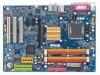
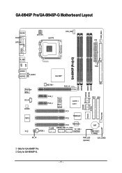
Only for GA-8I945P Pro. GA-8I945P Pro/GA-8I945P-G Motherboard Layout KB_MS ATX_12V CPU_FAN COAXIAL LGA775 ATX OPTICAL PWR_FAN LPT LAN COMA GA-8I945P (Pro)(-G) R_USB USB FDD AUDIO1 AUDIO2 F_AUDIO Intel 945P Broadcom 5789 CD_IN CODEC IT8712 NB_FAN PCIE_16 PCIE_1 PCIE_2 Main BIOS Back BIOS ICH7R / ICH7 PCI1 TSB82AA2 PCI2 SATAII0 IT8212 SATAII1 DDRII1 DDRII2 SATAII2 SATAII3 DDRII3 DDRII4 IDE1 IDE3 IDE2 SYS_FAN PCI3 TSB81BA3 BAT F_USB GREEN_USB F1_1394 F2_1394 CI SPDIF_I F_PANEL RF_ID PWR_LED (Optional) CLR_CMOS Only for GA-8I945P-G. - 7 -
Only for GA-8I945P Pro. GA-8I945P Pro/GA-8I945P-G Motherboard Layout KB_MS ATX_12V CPU_FAN COAXIAL LGA775 ATX OPTICAL PWR_FAN LPT LAN COMA GA-8I945P (Pro)(-G) R_USB USB FDD AUDIO1 AUDIO2 F_AUDIO Intel 945P Broadcom 5789 CD_IN CODEC IT8712 NB_FAN PCIE_16 PCIE_1 PCIE_2 Main BIOS Back BIOS ICH7R / ICH7 PCI1 TSB82AA2 PCI2 SATAII0 IT8212 SATAII1 DDRII1 DDRII2 SATAII2 SATAII3 DDRII3 DDRII4 IDE1 IDE3 IDE2 SYS_FAN PCI3 TSB81BA3 BAT F_USB GREEN_USB F1_1394 F2_1394 CI SPDIF_I F_PANEL RF_ID PWR_LED (Optional) CLR_CMOS Only for GA-8I945P-G. - 7 -
Manual
Page 8
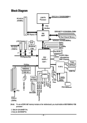
... In SPDIF Out PCICLK (33MHz) (Note) To use a DDRII 667 memory module on the motherboard, you must install an 800/1066MHz FSB processor . Only for GA-8I945P Pro. Only for GA-8I945P-G. - 8 -
... In SPDIF Out PCICLK (33MHz) (Note) To use a DDRII 667 memory module on the motherboard, you must install an 800/1066MHz FSB processor . Only for GA-8I945P Pro. Only for GA-8I945P-G. - 8 -
Manual
Page 10
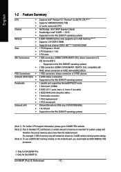
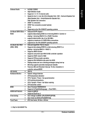
... 3.xxGB memory during system startup. (Note 3) To use a DDRII 667 memory module on the motherboard, you must install an 800/1066MHz FSB processor . Only for GA-8I945P-G. GA-8I945P (Pro)(-G) Motherboard - 10 - English 1-2 Feature Summary CPU Š Š Š Chipset Š Š Š Memory Š Š Š Slots... Mbit) 1 RJ 45 port Supported on the Win 2000/XP operating systems (Note 1) For further CPU support information, please go to GIGABYTE's website. (Note 2) Due to 4GB memory) (Note 2) Supports 1.8V DDR II DIMM Supports dual channel DDR II 667(Note 3)/533...
... 3.xxGB memory during system startup. (Note 3) To use a DDRII 667 memory module on the motherboard, you must install an 800/1066MHz FSB processor . Only for GA-8I945P-G. GA-8I945P (Pro)(-G) Motherboard - 10 - English 1-2 Feature Summary CPU Š Š Š Chipset Š Š Š Memory Š Š Š Slots... Mbit) 1 RJ 45 port Supported on the Win 2000/XP operating systems (Note 1) For further CPU support information, please go to GIGABYTE's website. (Note 2) Due to 4GB memory) (Note 2) Supports 1.8V DDR II DIMM Supports dual channel DDR II 667(Note 3)/533...
Manual
Page 11
... EasyTune 5 Over Voltage via BIOS (CPU/DDR/PCIE/FSB) Over Clock via BIOS (CPU/DDR/PCIE) ATX form factor; 30.5cm x 22.0cm Only for GA-8I945P Pro. - 11 - MIC ;
... EasyTune 5 Over Voltage via BIOS (CPU/DDR/PCIE/FSB) Over Clock via BIOS (CPU/DDR/PCIE) ATX form factor; 30.5cm x 22.0cm Only for GA-8I945P Pro. - 11 - MIC ;
Manual
Page 12
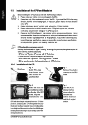
... its original position. It is installed on the CPU socket. Please set beyond the proper specifications, please do so according to the CPU during installation.) GA-8I945P (Pro)(-G) Motherboard - 12 - Chipset: An Intel® Chipset that the motherboard supports the CPU. 2. BIOS: A BIOS that the system bus frequency be set the CPU host...
... its original position. It is installed on the CPU socket. Please set beyond the proper specifications, please do so according to the CPU during installation.) GA-8I945P (Pro)(-G) Motherboard - 12 - Chipset: An Intel® Chipset that the motherboard supports the CPU. 2. BIOS: A BIOS that the system bus frequency be set the CPU host...
Manual
Page 14
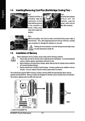
... fan, carefully use a screwdriver to a heatsink, align the extensions on both sides with the grooves in the heatsink as shown. GA-8I945P (Pro)(-G) Motherboard - 14 - Before installing or removing memory modules, please make sure that the fan's power cable is disconnected. If you...used can be used is switched off . 1-5 Installation of similar capacity, specifications and brand be installed in one direction. Only for GA-8I945P Pro. English 1-4 Installing/Removing Cool-Plus (Northbridge Cooling Fan) Fig.1 To attach Cool-Plus to dislodge the extension on one side. Fig...
... fan, carefully use a screwdriver to a heatsink, align the extensions on both sides with the grooves in the heatsink as shown. GA-8I945P (Pro)(-G) Motherboard - 14 - Before installing or removing memory modules, please make sure that the fan's power cable is disconnected. If you...used can be used is switched off . 1-5 Installation of similar capacity, specifications and brand be installed in one direction. Only for GA-8I945P Pro. English 1-4 Installing/Removing Cool-Plus (Northbridge Cooling Fan) Fig.1 To attach Cool-Plus to dislodge the extension on one side. Fig...
Manual
Page 15
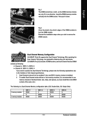
Insert the DIMM memory module vertically into DIMM sockets of the same color. Dual Channel Memory Configuration GA-8I945P (Pro)(-G) supports the Dual Channel Technology. To enable Dual Channel mode with two or four memory modules (it down. Reverse the installation steps when you wish ...to lock the DIMM module. Fig.2 Close the plastic clip at both edges of the DIMM sockets to remove the DIMM module. GA-8I945P (Pro)(-G) includes 4 DIMM sockets, and each Channel has two DIMM sockets as following: Channel A : DDR II 1, DDR II 2 Channel B : DDR II 3, DDR II 4 If you must...
Insert the DIMM memory module vertically into DIMM sockets of the same color. Dual Channel Memory Configuration GA-8I945P (Pro)(-G) supports the Dual Channel Technology. To enable Dual Channel mode with two or four memory modules (it down. Reverse the installation steps when you wish ...to lock the DIMM module. Fig.2 Close the plastic clip at both edges of the DIMM sockets to remove the DIMM module. GA-8I945P (Pro)(-G) includes 4 DIMM sockets, and each Channel has two DIMM sockets as following: Channel A : DDR II 1, DDR II 2 Channel B : DDR II 3, DDR II 4 If you must...
Manual
Page 16
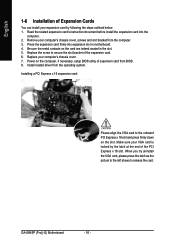
... by the latch at the end of the PCI Express x 16 slot. Power on the computer, if necessary, setup BIOS utility of the expansion card. 6. GA-8I945P (Pro)(-G) Motherboard - 16 -
... by the latch at the end of the PCI Express x 16 slot. Power on the computer, if necessary, setup BIOS utility of the expansion card. 6. GA-8I945P (Pro)(-G) Motherboard - 16 -
Manual
Page 18
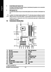
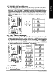
... 12 1) ATX_12V 2) ATX (Power Connector) 3) CPU_FAN 4) SYS_FAN 5) PWR_FAN 6) NB_FAN 7) FDD 8) IDE1/IDE2/IDE3 9) SATAII0 / SATAII1 / SATAII2 / SATAII3 10) F_AUDIO Only for GA-8I945P Pro. Center/Subwoofer speakers can be connected to the de- fault Mic In jack ( ) . PWR_LED (Optional) F_PANEL CD_IN SPDIF_I F_USB/GREEN_USB F1_1394/F2_1394 RF_ID CI CLR_CMOS... different functions via the audio software. In addition to the default speakers settings, the ~ audio jacks can be reconfigured to the 2-/4-/6-/8- GA-8I945P (Pro)(-G) Motherboard 11) 12) 13) 14) 15) 16) 17) 18) 19) 20) - 18 -
... 12 1) ATX_12V 2) ATX (Power Connector) 3) CPU_FAN 4) SYS_FAN 5) PWR_FAN 6) NB_FAN 7) FDD 8) IDE1/IDE2/IDE3 9) SATAII0 / SATAII1 / SATAII2 / SATAII3 10) F_AUDIO Only for GA-8I945P Pro. Center/Subwoofer speakers can be connected to the de- fault Mic In jack ( ) . PWR_LED (Optional) F_PANEL CD_IN SPDIF_I F_USB/GREEN_USB F1_1394/F2_1394 RF_ID CI CLR_CMOS... different functions via the audio software. In addition to the default speakers settings, the ~ audio jacks can be reconfigured to the 2-/4-/6-/8- GA-8I945P (Pro)(-G) Motherboard 11) 12) 13) 14) 15) 16) 17) 18) 19) 20) - 18 -

Manual
Page 20
... power voltage. Caution! English 3/4/5) CPU_FAN / SYS_FAN / PWR_FAN (Cooler Fan Power Connector) The cooler fan power connector supplies a +12V power voltage via a 3-pin/4-pin (only for GA-8I945P Pro. GA-8I945P (Pro)(-G) Motherboard - 20 - The black connector wire is GND) Pin No. Please remember to connect the power to the CPU fan to prevent system overheating and...
... power voltage. Caution! English 3/4/5) CPU_FAN / SYS_FAN / PWR_FAN (Cooler Fan Power Connector) The cooler fan power connector supplies a +12V power voltage via a 3-pin/4-pin (only for GA-8I945P Pro. GA-8I945P (Pro)(-G) Motherboard - 20 - The black connector wire is GND) Pin No. Please remember to connect the power to the CPU fan to prevent system overheating and...
Manual
Page 22
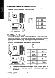
... the BIOS setting for the Serial ATA II and install the proper driver in order to the instructions on Page 78 about the software settings. GA-8I945P (Pro)(-G) Motherboard - 22 - Check the pin assignments carefully while you wish to use the front audio function, connect the front panel audio module to this connector...
... the BIOS setting for the Serial ATA II and install the proper driver in order to the instructions on Page 78 about the software settings. GA-8I945P (Pro)(-G) Motherboard - 22 - Check the pin assignments carefully while you wish to use the front audio function, connect the front panel audio module to this connector...
Manual
Page 24
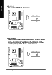
Be careful with the polarity of the SPDIF_IN connector. Definition 1 Power 1 2 SPDIFI 3 GND GA-8I945P (Pro)(-G) Motherboard - 24 - English 13) CD_IN (CD IN) Connect CD-ROM or DVD-ROM audio out to work or even damage it. Definition 1 CD-L 1 2 GND 3 GND 4 ...
Be careful with the polarity of the SPDIF_IN connector. Definition 1 Power 1 2 SPDIFI 3 GND GA-8I945P (Pro)(-G) Motherboard - 24 - English 13) CD_IN (CD IN) Connect CD-ROM or DVD-ROM audio out to work or even damage it. Definition 1 CD-L 1 2 GND 3 GND 4 ...
Manual
Page 25
... USB/GREEN_USB (Front USB Connector) Be careful with the polarity of the IEEE1394 connector. Users who wish to shut down the standby power(note) for GA-8I945P Pro. 1 F1_1394 2 1 Pin No. 1 2 3 4 5 6 7 8 9 10 15 10 9 Definition TPA2+ TPA2GND GND TPB2+ TPB2No Pin Power Power GND 2 Power 3 TPA0+ 4 TPA0- 5 GND 6 GND 7 TPB0+ 8 TPB0- 9 Power 10...
... USB/GREEN_USB (Front USB Connector) Be careful with the polarity of the IEEE1394 connector. Users who wish to shut down the standby power(note) for GA-8I945P Pro. 1 F1_1394 2 1 Pin No. 1 2 3 4 5 6 7 8 9 10 15 10 9 Definition TPA2+ TPA2GND GND TPB2+ TPB2No Pin Power Power GND 2 Power 3 TPA0+ 4 TPA0- 5 GND 6 GND 7 TPB0+ 8 TPB0- 9 Power 10...
Manual
Page 26
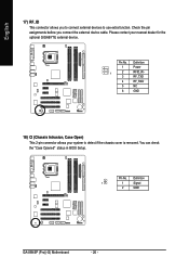
... 1 2 RFID_RI- 3 RF_TXD 4 RF_RXD 5 NC 6 GND 18) CI (Chassis Intrusion, Case Open) This 2-pin connector allows your nearest dealer for the optional GIGABYTE external device. Pin No. Definition 1 1 Signal 2 GND GA-8I945P (Pro)(-G) Motherboard - 26 - English 17) RF_ID This connector allows you connect the external device cable. Pin No. You can check the "Case Opened...
... 1 2 RFID_RI- 3 RF_TXD 4 RF_RXD 5 NC 6 GND 18) CI (Chassis Intrusion, Case Open) This 2-pin connector allows your nearest dealer for the optional GIGABYTE external device. Pin No. Definition 1 1 Signal 2 GND GA-8I945P (Pro)(-G) Motherboard - 26 - English 17) RF_ID This connector allows you connect the external device cable. Pin No. You can check the "Case Opened...
Manual
Page 28
English GA-8I945P (Pro)(-G) Motherboard - 28 -
English GA-8I945P (Pro)(-G) Motherboard - 28 -
Manual
Page 29
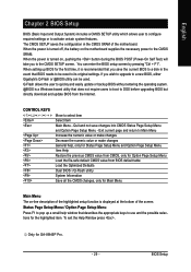
.... Exit current page and return to the CMOS SETUP screen. To exit the Help Window press . If you wish to upgrade to a new BIOS, either Gigabyte's Q-Flash or @BIOS utility can enter the BIOS setup screen by pressing "Ctrl + F1". Only for Option Page Setup Menu Load the file-safe default... changes General help, only for Status Page Setup Menu and Option Page Setup Menu Item Help Restore the previous CMOS value from CMOS, only for GA-8I945P Pro. - 29 - Quit and not save the current BIOS to a disk in the CMOS SRAM of the screen. BIOS Setup You can be reset to be...
.... Exit current page and return to the CMOS SETUP screen. To exit the Help Window press . If you wish to upgrade to a new BIOS, either Gigabyte's Q-Flash or @BIOS utility can enter the BIOS setup screen by pressing "Ctrl + F1". Only for Option Page Setup Menu Load the file-safe default... changes General help, only for Status Page Setup Menu and Option Page Setup Menu Item Help Restore the previous CMOS value from CMOS, only for GA-8I945P Pro. - 29 - Quit and not save the current BIOS to a disk in the CMOS SRAM of the screen. BIOS Setup You can be reset to be...
