Manual
Page 2
...GigaRAID controller, you may prepare only one hard drive. (b) An empty formatted floppy disk. (c) Windows XP/2000 setup disk. (d) Driver CD for your motherboard. (1) Installing IDE hard drive(s) in your computer. (2) Configure GigaRAID controller mode and boot sequence in BIOS Setup. (3)* Configure RAID set up IDE ... the IDE RAID controller driver during OS installation. Then connect the power connector from your power supply to create RAID array on the motherboard. (To ensure that your IDE CD-ROM drive can work properly, please connect it is recommended that you do not want to ...
...GigaRAID controller, you may prepare only one hard drive. (b) An empty formatted floppy disk. (c) Windows XP/2000 setup disk. (d) Driver CD for your motherboard. (1) Installing IDE hard drive(s) in your computer. (2) Configure GigaRAID controller mode and boot sequence in BIOS Setup. (3)* Configure RAID set up IDE ... the IDE RAID controller driver during OS installation. Then connect the power connector from your power supply to create RAID array on the motherboard. (To ensure that your IDE CD-ROM drive can work properly, please connect it is recommended that you do not want to ...
Manual
Page 3
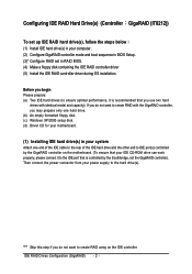
...Integrated Peripherals is set GigaRAID Function to enter BIOS Setup during POST (Power-On Self Test). If you will see shall depend on your motherboard. CMOS Setup Utility-Copyright (C) 1984-2004 Award Software Integrated Peripherals : Move Enter: Select F5: Previous Values +/-/PU/PD: Value F10: ...the IDE RAID hard drive(s). IDE RAID Drives Configuration (GigaRAID) If you have to RAID (Figure 1). Step 1: Turn on the motherboard you want to create RAID, set to Enabled and GigaRAID Function to make sure whether the GigaRAID controller are configured correctly in system ...
...Integrated Peripherals is set GigaRAID Function to enter BIOS Setup during POST (Power-On Self Test). If you will see shall depend on your motherboard. CMOS Setup Utility-Copyright (C) 1984-2004 Award Software Integrated Peripherals : Move Enter: Select F5: Previous Values +/-/PU/PD: Value F10: ...the IDE RAID hard drive(s). IDE RAID Drives Configuration (GigaRAID) If you have to RAID (Figure 1). Step 1: Turn on the motherboard you want to create RAID, set to Enabled and GigaRAID Function to make sure whether the GigaRAID controller are configured correctly in system ...
Manual
Page 14
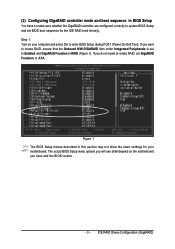
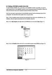
...ROM drive. Ác (4) Making a IDE RAID controller driver disk Åé To install Windows 2000/XP onto a hard drive on your motherboard during the Windows setup process. ¤å First of all, you need to install required driver for the GigaRAID controller on the GigaRAID controller ...successfully, you need to copy the driver for the IDE RAID controller from the motherboard driver CD to a floppydisk. Step 2: Go to the BootDrv folder and look for an executable program named MENU.exe (Figure 17)....
...ROM drive. Ác (4) Making a IDE RAID controller driver disk Åé To install Windows 2000/XP onto a hard drive on your motherboard during the Windows setup process. ¤å First of all, you need to install required driver for the GigaRAID controller on the GigaRAID controller ...successfully, you need to copy the driver for the IDE RAID controller from the motherboard driver CD to a floppydisk. Step 2: Go to the BootDrv folder and look for an executable program named MENU.exe (Figure 17)....
Manual
Page 15
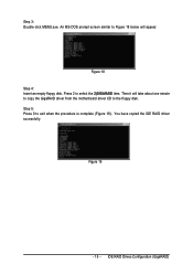
Figure 18 Step 4: Insert an empty floppy disk. You have copied the IDE RAID driver sucessfully. Step 3: Double-click MENU.exe. Then it will appear. IDE RAID Drives Configuration (GigaRAID) Press 2 to exit when the procedure is complete (Figure 19). Figure 19 - 15 - An MS-DOS prompt screen similar to Figure 18 below will take about one minute to copy the GigaRAID driver from the motherboard driver CD to the floppy disk. Step 5: Press 0 to select the 2)GIGARAID item.
Figure 18 Step 4: Insert an empty floppy disk. You have copied the IDE RAID driver sucessfully. Step 3: Double-click MENU.exe. Then it will appear. IDE RAID Drives Configuration (GigaRAID) Press 2 to exit when the procedure is complete (Figure 19). Figure 19 - 15 - An MS-DOS prompt screen similar to Figure 18 below will take about one minute to copy the GigaRAID driver from the motherboard driver CD to the floppy disk. Step 5: Press 0 to select the 2)GIGARAID item.
Manual
Page 17
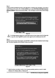
... appears saying one minute. The driver installation will be found, please check the floppy disk or copy the correct GigaRAID controller driver again from the motherboard driver CD. Step 3: If Setup correctly recognizes the driver in about one or some file(s) cannot be finished in the floppy disk, a controller menu will...
... appears saying one minute. The driver installation will be found, please check the floppy disk or copy the correct GigaRAID controller driver again from the motherboard driver CD. Step 3: If Setup correctly recognizes the driver in about one or some file(s) cannot be finished in the floppy disk, a controller menu will...
Manual
Page 72
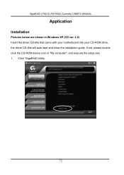
Click "GigaRAID Utility. 72 GigaRAID (IT8212) ATA RAID Controller USER'S MANUAL Application Installation Pictures below are shown in "My computer", and execute the setup.exe. 1. If not, please double click the CD-ROM device icon in Windows XP (CD ver. 2.2) Insert the driver CD-title that came with your motherboard into your CD-ROM drive, the driver CD-title will auto start and show the installation guide.
Click "GigaRAID Utility. 72 GigaRAID (IT8212) ATA RAID Controller USER'S MANUAL Application Installation Pictures below are shown in "My computer", and execute the setup.exe. 1. If not, please double click the CD-ROM device icon in Windows XP (CD ver. 2.2) Insert the driver CD-title that came with your motherboard into your CD-ROM drive, the driver CD-title will auto start and show the installation guide.
Manual
Page 1
GA-8I945P Pro/ GA-8I945P-G Intel® Pentium® D / Pentium® 4 LGA775 Processor Motherboard User's Manual Rev. 1005 12ME-8I945PP-1005 * The WEEE marking on the product indicates this product must not be disposed of with user's other household waste and must be handed over to a designated collection point for the recycling of waste electrical and electronic equipment!! * The WEEE marking applies only in European Union's member states.
GA-8I945P Pro/ GA-8I945P-G Intel® Pentium® D / Pentium® 4 LGA775 Processor Motherboard User's Manual Rev. 1005 12ME-8I945PP-1005 * The WEEE marking on the product indicates this product must not be disposed of with user's other household waste and must be handed over to a designated collection point for the recycling of waste electrical and electronic equipment!! * The WEEE marking applies only in European Union's member states.
Manual
Page 2
Motherboard GA-8I945P Pro/GA-8I945P-G Apr. 18, 2005 Motherboard GA-8I945P Pro/GA-8I945P-G Apr. 18, 2005
Motherboard GA-8I945P Pro/GA-8I945P-G Apr. 18, 2005 Motherboard GA-8I945P Pro/GA-8I945P-G Apr. 18, 2005
Manual
Page 4
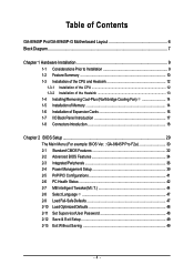
Table of Contents GA-8I945P Pro/GA-8I945P-G Motherboard Layout 6 Block Diagram ...7 Chapter 1 Hardware Installation 9 1-1 Considerations Prior to Installation 9 1-2 Feature Summary 10 1-3 Installation of the CPU and Heatsink 12 1-3-1 Installation... of Expansion Cards 16 1-7 I/O Back Panel Introduction 17 1-8 Connectors Introduction 18 Chapter 2 BIOS Setup 29 The Main Menu (For example: BIOS Ver. : GA-8I945P Pro F2a 30 2-1 Standard CMOS Features 32 2-2 Advanced BIOS Features 34 2-3 IntegratedPeripherals 36 2-4 Power Management Setup 39 2-5 PnP/PCI Configurations 41 2-6 PC Health...
Table of Contents GA-8I945P Pro/GA-8I945P-G Motherboard Layout 6 Block Diagram ...7 Chapter 1 Hardware Installation 9 1-1 Considerations Prior to Installation 9 1-2 Feature Summary 10 1-3 Installation of the CPU and Heatsink 12 1-3-1 Installation... of Expansion Cards 16 1-7 I/O Back Panel Introduction 17 1-8 Connectors Introduction 18 Chapter 2 BIOS Setup 29 The Main Menu (For example: BIOS Ver. : GA-8I945P Pro F2a 30 2-1 Standard CMOS Features 32 2-2 Advanced BIOS Features 34 2-3 IntegratedPeripherals 36 2-4 Power Management Setup 39 2-5 PnP/PCI Configurations 41 2-6 PC Health...
Manual
Page 7
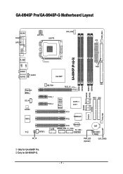
GA-8I945P Pro/GA-8I945P-G Motherboard Layout KB_MS ATX_12V CPU_FAN COAXIAL LGA775 ATX OPTICAL PWR_FAN LPT LAN COMA GA-8I945P (Pro)(-G) R_USB USB FDD AUDIO1 AUDIO2 F_AUDIO Intel 945P Broadcom 5789 CD_IN CODEC IT8712 NB_FAN PCIE_16 PCIE_1 PCIE_2 Main BIOS Back BIOS ICH7R / ICH7 PCI1 TSB82AA2 PCI2 SATAII0 IT8212 SATAII1 DDRII1 DDRII2 SATAII2 SATAII3 DDRII3 DDRII4 IDE1 IDE3 IDE2 SYS_FAN PCI3 TSB81BA3 BAT F_USB GREEN_USB F1_1394 F2_1394 CI SPDIF_I F_PANEL RF_ID PWR_LED (Optional) CLR_CMOS Only for GA-8I945P-G. - 7 - Only for GA-8I945P Pro.
GA-8I945P Pro/GA-8I945P-G Motherboard Layout KB_MS ATX_12V CPU_FAN COAXIAL LGA775 ATX OPTICAL PWR_FAN LPT LAN COMA GA-8I945P (Pro)(-G) R_USB USB FDD AUDIO1 AUDIO2 F_AUDIO Intel 945P Broadcom 5789 CD_IN CODEC IT8712 NB_FAN PCIE_16 PCIE_1 PCIE_2 Main BIOS Back BIOS ICH7R / ICH7 PCI1 TSB82AA2 PCI2 SATAII0 IT8212 SATAII1 DDRII1 DDRII2 SATAII2 SATAII3 DDRII3 DDRII4 IDE1 IDE3 IDE2 SYS_FAN PCI3 TSB81BA3 BAT F_USB GREEN_USB F1_1394 F2_1394 CI SPDIF_I F_PANEL RF_ID PWR_LED (Optional) CLR_CMOS Only for GA-8I945P-G. - 7 - Only for GA-8I945P Pro.
Manual
Page 8
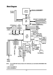
... Speaker Out Side Speaker Out MIC Line-Out Line-In SPDIF In SPDIF Out PCICLK (33MHz) (Note) To use a DDRII 667 memory module on the motherboard, you must install an 800/1066MHz FSB processor . Only for GA-8I945P-G. - 8 - Only for GA-8I945P Pro.
... Speaker Out Side Speaker Out MIC Line-Out Line-In SPDIF In SPDIF Out PCICLK (33MHz) (Note) To use a DDRII 667 memory module on the motherboard, you must install an 800/1066MHz FSB processor . Only for GA-8I945P-G. - 8 - Only for GA-8I945P Pro.
Manual
Page 9
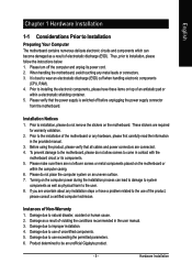
... make sure there are uncertain about any installation steps or have these items on top of electrostatic discharge (ESD). Instances of the motherboard or any metal leads or connectors. 3. Damage due to use exceeding the permitted parameters. 6. It is switched off the computer ...due to use of the product, please consult a certified computer technician. Hardware Installation Thus, prior to be an unofficial Gigabyte product. - 9 - When handling the motherboard, avoid touching any hardware, please first carefully read the information in the provided manual. 3. Damage as a result of...
... make sure there are uncertain about any installation steps or have these items on top of electrostatic discharge (ESD). Instances of the motherboard or any metal leads or connectors. 3. Damage due to use exceeding the permitted parameters. 6. It is switched off the computer ...due to use of the product, please consult a certified computer technician. Hardware Installation Thus, prior to be an unofficial Gigabyte product. - 9 - When handling the motherboard, avoid touching any hardware, please first carefully read the information in the provided manual. 3. Damage as a result of...
Manual
Page 10
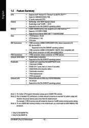
...3.xxGB memory during system startup. (Note 3) To use a DDRII 667 memory module on the motherboard, you must install an 800/1066MHz FSB processor . Only for GA-8I945P-G. Only for GA-8I945P Pro. English 1-2 Feature Summary CPU Š Š Š Chipset Š Š...GIGABYTE's website. (Note 2) Due to 4GB memory) (Note 2) Supports 1.8V DDR II DIMM Supports dual channel DDR II 667(Note 3)/533/400 DIMM 1 PCI Express x 16 slot 2 PCI Express x 1 slot 3 PCI slots 1 IDE connection (UDMA 33/ATA 66/ATA 100), allows connection of 2 IDE devices(IDE1) - GA-8I945P (Pro)(-G) Motherboard...
...3.xxGB memory during system startup. (Note 3) To use a DDRII 667 memory module on the motherboard, you must install an 800/1066MHz FSB processor . Only for GA-8I945P-G. Only for GA-8I945P Pro. English 1-2 Feature Summary CPU Š Š Š Chipset Š Š...GIGABYTE's website. (Note 2) Due to 4GB memory) (Note 2) Supports 1.8V DDR II DIMM Supports dual channel DDR II 667(Note 3)/533/400 DIMM 1 PCI Express x 16 slot 2 PCI Express x 1 slot 3 PCI slots 1 IDE connection (UDMA 33/ATA 66/ATA 100), allows connection of 2 IDE devices(IDE1) - GA-8I945P (Pro)(-G) Motherboard...
Manual
Page 12
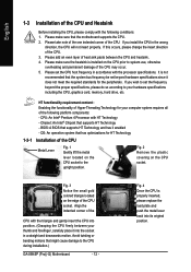
... card, memory, hard drive, etc. Fig. 3 Notice the small gold colored triangle located on the CPU prior to the CPU during installation.) GA-8I945P (Pro)(-G) Motherboard - 12 - Avoid twisting or bending motions that supports HT Technology - Fig. 4 Once the CPU is properly inserted, please replace the load ... Lever Fig. 1 Gently lift the metal lever located on the CPU socket. Please make sure the heatsink is not recommended that the motherboard supports the CPU. 2. If you wish to set beyond the proper specifications, please do so according to the upright position. CPU: An...
... card, memory, hard drive, etc. Fig. 3 Notice the small gold colored triangle located on the CPU prior to the CPU during installation.) GA-8I945P (Pro)(-G) Motherboard - 12 - Avoid twisting or bending motions that supports HT Technology - Fig. 4 Once the CPU is properly inserted, please replace the load ... Lever Fig. 1 Gently lift the metal lever located on the CPU socket. Please make sure the heatsink is not recommended that the motherboard supports the CPU. 2. If you wish to set beyond the proper specifications, please do so according to the upright position. CPU: An...
Manual
Page 13
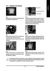
... please attach the power connector of the installed CPU. Fig. 4 Please make sure the push pins aim to the pin hole on the motherboard.Pressing down the push pins diagonally. English 1-3-2 Installation of the Heatsink Male Push Pin The top of Female Push Pin Female Push Pin Fig.1... either thermal tape rather than heat sink paste be used for detailed installation instructions, please refer to install.) Please note the direction of motherboard after installing. Hardware Installation Fig. 2 (Turning the push pin along the direction of arrow is to remove the heatsink, on the contrary...
... please attach the power connector of the installed CPU. Fig. 4 Please make sure the push pins aim to the pin hole on the motherboard.Pressing down the push pins diagonally. English 1-3-2 Installation of the Heatsink Male Push Pin The top of Female Push Pin Female Push Pin Fig.1... either thermal tape rather than heat sink paste be used for detailed installation instructions, please refer to install.) Please note the direction of motherboard after installing. Hardware Installation Fig. 2 (Turning the push pin along the direction of arrow is to remove the heatsink, on the contrary...
Manual
Page 14
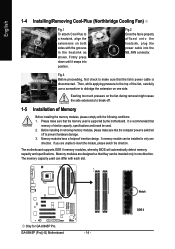
...insert the module, please switch the direction. If you are designed so that the memory used . 2. The motherboard supports DDR II memory modules, whereby BIOS will automatically detect memory capacity and specifications. Notch DDR II Please make...to make sure that they can be used is disconnected. Memory modules have a foolproof insertion design. Only for GA-8I945P Pro. English 1-4 Installing/Removing Cool-Plus (Northbridge Cooling Fan) Fig.1 To attach Cool-Plus to dislodge the... press down until it snaps into the NB_FAN connector. GA-8I945P (Pro)(-G) Motherboard - 14 -
...insert the module, please switch the direction. If you are designed so that the memory used . 2. The motherboard supports DDR II memory modules, whereby BIOS will automatically detect memory capacity and specifications. Notch DDR II Please make...to make sure that they can be used is disconnected. Memory modules have a foolproof insertion design. Only for GA-8I945P Pro. English 1-4 Installing/Removing Cool-Plus (Northbridge Cooling Fan) Fig.1 To attach Cool-Plus to dislodge the... press down until it snaps into the NB_FAN connector. GA-8I945P (Pro)(-G) Motherboard - 14 -
Manual
Page 16
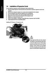
... card from BIOS. 8. Press the expansion card firmly into the computer. 2. Power on the computer, if necessary, setup BIOS utility of the expansion card. 6. GA-8I945P (Pro)(-G) Motherboard - 16 - Read the related expansion card's instruction document before install the expansion card into expansion slot in the slot. 5. Make sure your computer's chassis cover...
... card from BIOS. 8. Press the expansion card firmly into the computer. 2. Power on the computer, if necessary, setup BIOS utility of the expansion card. 6. GA-8I945P (Pro)(-G) Motherboard - 16 - Read the related expansion card's instruction document before install the expansion card into expansion slot in the slot. 5. Make sure your computer's chassis cover...
Manual
Page 18
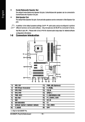
... (Power Connector) 3) CPU_FAN 4) SYS_FAN 5) PWR_FAN 6) NB_FAN 7) FDD 8) IDE1/IDE2/IDE3 9) SATAII0 / SATAII1 / SATAII2 / SATAII3 10) F_AUDIO Only for GA-8I945P Pro. Please refer to Center/Subwoofer Speaker Out jack. fault Mic In jack ( ) . GA-8I945P (Pro)(-G) Motherboard 11) 12) 13) 14) 15) 16) 17) 18) 19) 20) - 18 - PWR_LED (Optional) F_PANEL CD_IN SPDIF_I F_USB/GREEN_USB...
... (Power Connector) 3) CPU_FAN 4) SYS_FAN 5) PWR_FAN 6) NB_FAN 7) FDD 8) IDE1/IDE2/IDE3 9) SATAII0 / SATAII1 / SATAII2 / SATAII3 10) F_AUDIO Only for GA-8I945P Pro. Please refer to Center/Subwoofer Speaker Out jack. fault Mic In jack ( ) . GA-8I945P (Pro)(-G) Motherboard 11) 12) 13) 14) 15) 16) 17) 18) 19) 20) - 18 - PWR_LED (Optional) F_PANEL CD_IN SPDIF_I F_USB/GREEN_USB...

Manual
Page 19
... 18 GND 19 GND 20 -5V 21 +5V 22 +5V 23 +5V 24 GND - 19 - Align the power connector with its proper location on the motherboard before plugging in the power cord ; Please use a 24-pin ATX power supply, please remove the small cover on the power connector on the... motherboard and connect tightly. It is recommended that a power supply that can lead to the CPU. Pin No. Before connecting the power connector, please make sure ...
... 18 GND 19 GND 20 -5V 21 +5V 22 +5V 23 +5V 24 GND - 19 - Align the power connector with its proper location on the motherboard before plugging in the power cord ; Please use a 24-pin ATX power supply, please remove the small cover on the power connector on the... motherboard and connect tightly. It is recommended that a power supply that can lead to the CPU. Pin No. Before connecting the power connector, please make sure ...

Manual
Page 20
... the power to the cooler to prevent CPU overheating and failure. 1 CPU_FAN 1 SYS_FAN/ PWR_FAN Pin No. 1 2 3 4 Definition GND +12V Sense Speed Control (Only for GA-8I945P Pro. GA-8I945P (Pro)(-G) Motherboard - 20 - Caution! Most coolers are designed with color-coded power connector wires. The black connector wire is GND) Pin No. Please remember to connect...
... the power to the cooler to prevent CPU overheating and failure. 1 CPU_FAN 1 SYS_FAN/ PWR_FAN Pin No. 1 2 3 4 Definition GND +12V Sense Speed Control (Only for GA-8I945P Pro. GA-8I945P (Pro)(-G) Motherboard - 20 - Caution! Most coolers are designed with color-coded power connector wires. The black connector wire is GND) Pin No. Please remember to connect...


