Manual
Page 1
GA-8I945G Pro/ GA-8I945G Intel® Pentium® D / Pentium® 4 LGA775 Processor Motherboard User's Manual Rev. 1005 12ME-8I945GP-1005 * The WEEE marking on the product indicates this product must not be disposed of with user's other household waste and must be handed over to a designated collection point for the recycling of waste electrical and electronic equipment!! * The WEEE marking applies only in European Union's member states.
GA-8I945G Pro/ GA-8I945G Intel® Pentium® D / Pentium® 4 LGA775 Processor Motherboard User's Manual Rev. 1005 12ME-8I945GP-1005 * The WEEE marking on the product indicates this product must not be disposed of with user's other household waste and must be handed over to a designated collection point for the recycling of waste electrical and electronic equipment!! * The WEEE marking applies only in European Union's member states.

Manual
Page 4
Table of Contents GA-8I945G Pro Motherboard Layout 6 GA-8I945G Motherboard Layout 7 Block Diagram ...8 Chapter 1 Hardware Installation 9 1-1 Considerations Prior to Installation 9 1-2 Feature Summary 10 1-3 Installation of the CPU and ... of Expansion Cards 16 1-7 I/O Back Panel Introduction 17 1-8 Connectors Introduction 18 Chapter 2 BIOS Setup 29 The Main Menu (For example: BIOS Ver. : GA-8I945G Pro F2d 30 2-1 Standard CMOS Features 32 2-2 Advanced BIOS Features 34 2-3 IntegratedPeripherals 36 2-4 Power Management Setup 39 2-5 PnP/PCI Configurations 41 2-6 PC Health Status...
Table of Contents GA-8I945G Pro Motherboard Layout 6 GA-8I945G Motherboard Layout 7 Block Diagram ...8 Chapter 1 Hardware Installation 9 1-1 Considerations Prior to Installation 9 1-2 Feature Summary 10 1-3 Installation of the CPU and ... of Expansion Cards 16 1-7 I/O Back Panel Introduction 17 1-8 Connectors Introduction 18 Chapter 2 BIOS Setup 29 The Main Menu (For example: BIOS Ver. : GA-8I945G Pro F2d 30 2-1 Standard CMOS Features 32 2-2 Advanced BIOS Features 34 2-3 IntegratedPeripherals 36 2-4 Power Management Setup 39 2-5 PnP/PCI Configurations 41 2-6 PC Health Status...
Manual
Page 5
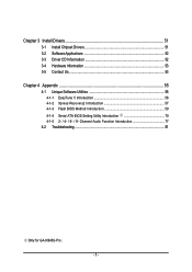
Chapter 3 Install Drivers 51 3-1 Install Chipset Drivers 51 3-2 SoftwareApplications 52 3-3 Driver CD Information 52 3-4 Hardware Information 53 3-5 Contact Us ...53 Chapter 4 Appendix 55 4-1 Unique Software Utilities 55 4-1-1 EasyTune 5 Introduction 56 4-1-2 Xpress Recovery2 Introduction 57 4-1-3 Flash BIOS Method Introduction 59 4-1-4 Serial ATA BIOS Setting Utility Introduction 70 4-1-5 2- / 4- / 6- / 8- Channel Audio Function Introduction 77 4-2 Troubleshooting 81 Only for GA-8I945G Pro. - 5 -
Chapter 3 Install Drivers 51 3-1 Install Chipset Drivers 51 3-2 SoftwareApplications 52 3-3 Driver CD Information 52 3-4 Hardware Information 53 3-5 Contact Us ...53 Chapter 4 Appendix 55 4-1 Unique Software Utilities 55 4-1-1 EasyTune 5 Introduction 56 4-1-2 Xpress Recovery2 Introduction 57 4-1-3 Flash BIOS Method Introduction 59 4-1-4 Serial ATA BIOS Setting Utility Introduction 70 4-1-5 2- / 4- / 6- / 8- Channel Audio Function Introduction 77 4-2 Troubleshooting 81 Only for GA-8I945G Pro. - 5 -

Manual
Page 6
GA-8I945G Pro Motherboard Layout KB_MS ATX_12V CPU_FAN COAXIAL LGA775 ATX OPTICAL PWR_FAN LPT LAN VGA GA-8I945G Pro R_USB USB FDD AUDIO1 AUDIO2 F_AUDIO Intel 945G Broadcom 5789 CD_IN CODEC IT8712 NB_FAN PCIE_16 PCIE_1 PCIE_2 Main BIOS Back BIOS ICH7R PCI1 TSB82AA2 PCI2 SATAII0 IT8212 SATAII1 DDRII1 DDRII2 SATAII2 SATAII3 DDRII3 DDRII4 IDE1 IDE3 IDE2 SYS_FAN COMA CI RF_ID SPDIF_I PCI3 TSB81BA3 BAT F_USB GREEN_USB F1_1394 F2_1394 F_PANEL PWR_LED (Optional) CLR_CMOS - 6 -
GA-8I945G Pro Motherboard Layout KB_MS ATX_12V CPU_FAN COAXIAL LGA775 ATX OPTICAL PWR_FAN LPT LAN VGA GA-8I945G Pro R_USB USB FDD AUDIO1 AUDIO2 F_AUDIO Intel 945G Broadcom 5789 CD_IN CODEC IT8712 NB_FAN PCIE_16 PCIE_1 PCIE_2 Main BIOS Back BIOS ICH7R PCI1 TSB82AA2 PCI2 SATAII0 IT8212 SATAII1 DDRII1 DDRII2 SATAII2 SATAII3 DDRII3 DDRII4 IDE1 IDE3 IDE2 SYS_FAN COMA CI RF_ID SPDIF_I PCI3 TSB81BA3 BAT F_USB GREEN_USB F1_1394 F2_1394 F_PANEL PWR_LED (Optional) CLR_CMOS - 6 -
Manual
Page 8
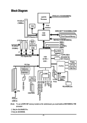
Only for GA-8I945G Pro. Only for GA-8I945G. - 8 - Block Diagram PCI-ECLK (100MHz) VGA PCI Express x16 2 PCI Express x1 RJ45 PCI-ECLK (100MHz) Broadcom 5789 x1 x1 x 1 PCI Express Bus PCI Bus ...
Only for GA-8I945G Pro. Only for GA-8I945G. - 8 - Block Diagram PCI-ECLK (100MHz) VGA PCI Express x16 2 PCI Express x1 RJ45 PCI-ECLK (100MHz) Broadcom 5789 x1 x1 x 1 PCI Express Bus PCI Bus ...

Manual
Page 10
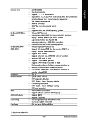
...chip (10/100/1000 Mbit) 1 RJ 45 port Supported on the Win 2000/XP operating systems (Note 1) For further CPU support information, please go to GIGABYTE's website. (Note 2) Due to 4GB memory) (Note 2) Supports 1.8V DDR II DIMM Supports dual channel DDR II 667(Note 3)/533/400 DIMM 1 PCI.../XP operating systems 4 DDR II DIMM memory slots (supports up to standard PC architecture, a certain amount of 2 IDE devices(IDE1) - Only for GA-8I945G Pro. Supported on the Win 2000/XP operating systems 2 IDE connection (UDMA 33/ATA 66/ATA 100/ATA 133), compatible with CPU Northbridge: Intel® ...
...chip (10/100/1000 Mbit) 1 RJ 45 port Supported on the Win 2000/XP operating systems (Note 1) For further CPU support information, please go to GIGABYTE's website. (Note 2) Due to 4GB memory) (Note 2) Supports 1.8V DDR II DIMM Supports dual channel DDR II 667(Note 3)/533/400 DIMM 1 PCI.../XP operating systems 4 DDR II DIMM memory slots (supports up to standard PC architecture, a certain amount of 2 IDE devices(IDE1) - Only for GA-8I945G Pro. Supported on the Win 2000/XP operating systems 2 IDE connection (UDMA 33/ATA 66/ATA 100/ATA 133), compatible with CPU Northbridge: Intel® ...
Manual
Page 11
...; Over Voltage via BIOS (CPU/DDR/PCIE/FSB) Š Over Clock via BIOS (CPU/DDR) Š ATX form factor; 30.5cm x 22.0cm Only for GA-8I945G Pro. - 11 - MIC ;
...; Over Voltage via BIOS (CPU/DDR/PCIE/FSB) Š Over Clock via BIOS (CPU/DDR) Š ATX form factor; 30.5cm x 22.0cm Only for GA-8I945G Pro. - 11 - MIC ;

Manual
Page 12
... and heatsink. 4. OS: An operation system that supports HT Technology - Fig. 4 Once the CPU is installed on the CPU socket to the CPU during installation.) GA-8I945G Pro/GA-8I945G Motherboard - 12 - Align the indented corner of the CPU Metal Lever Fig. 1 Gently lift the metal lever located on the CPU prior to your thumb...
... and heatsink. 4. OS: An operation system that supports HT Technology - Fig. 4 Once the CPU is installed on the CPU socket to the CPU during installation.) GA-8I945G Pro/GA-8I945G Motherboard - 12 - Align the indented corner of the CPU Metal Lever Fig. 1 Gently lift the metal lever located on the CPU prior to your thumb...
Manual
Page 14
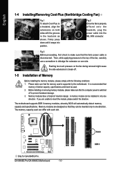
... modules are unable to make sure that the fan's power cable is properly affixed onto the heatsink, plug the power cable into position. GA-8I945G Pro/GA-8I945G Motherboard - 14 - Fig.2 Once the fan is disconnected. Memory modules have a foolproof insertion design. The motherboard supports DDR II memory... to the top of similar capacity, specifications and brand be inserted only in the heatsink as shown. Notch DDR II Only for GA-8I945G Pro. Then, while applying pressure to prevent hardware damage. 3. Exerting too much pressure on one direction. The memory capacity used is ...
... modules are unable to make sure that the fan's power cable is properly affixed onto the heatsink, plug the power cable into position. GA-8I945G Pro/GA-8I945G Motherboard - 14 - Fig.2 Once the fan is disconnected. Memory modules have a foolproof insertion design. The motherboard supports DDR II memory... to the top of similar capacity, specifications and brand be inserted only in the heatsink as shown. Notch DDR II Only for GA-8I945G Pro. Then, while applying pressure to prevent hardware damage. 3. Exerting too much pressure on one direction. The memory capacity used is ...
Manual
Page 15
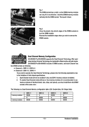
...DDR II 4 If you wish to lock the DIMM module. To enable Dual Channel mode with two or four memory modules (it down. GA-8I945G Pro/GA-8I945G includes 4 DIMM sockets, and each Channel has two DIMM sockets as following explanations due to use memory modules of the DIMM sockets to ...both edges of identical brand, size, chips, and speed), you must install them into the DIMM socket. Dual Channel Memory Configuration GA-8I945G Pro/GA-8I945G supports the Dual Channel Technology. Insert the DIMM memory module vertically into DIMM sockets of Memory Bus will not be enabled if only...
...DDR II 4 If you wish to lock the DIMM module. To enable Dual Channel mode with two or four memory modules (it down. GA-8I945G Pro/GA-8I945G includes 4 DIMM sockets, and each Channel has two DIMM sockets as following explanations due to use memory modules of the DIMM sockets to ...both edges of identical brand, size, chips, and speed), you must install them into the DIMM socket. Dual Channel Memory Configuration GA-8I945G Pro/GA-8I945G supports the Dual Channel Technology. Insert the DIMM memory module vertically into DIMM sockets of Memory Bus will not be enabled if only...

Manual
Page 16
... the VGA card, please press the latch as the picture to the left shows to secure the slot bracket of the PCI Express x 16 slot. GA-8I945G Pro/GA-8I945G Motherboard - 16 - English 1-6 Installation of expansion card from BIOS. 8. Power on the slot. Remove your computer's chassis cover. 7. Read the related expansion card's instruction document...
... the VGA card, please press the latch as the picture to the left shows to secure the slot bracket of the PCI Express x 16 slot. GA-8I945G Pro/GA-8I945G Motherboard - 16 - English 1-6 Installation of expansion card from BIOS. 8. Power on the slot. Remove your computer's chassis cover. 7. Read the related expansion card's instruction document...

Manual
Page 18
GA-8I945G Pro/GA-8I945G Motherboard - 18 - In addition to the default speakers settings, the ~ audio jacks can be connected to the default Mic In jack ( ) . channel audio setup steps ... 17) COMA 7) FDD 18) RF_ID 8) IDE1 / IDE2 / IDE3 19) CI 9) SATAII0 / SATAII1 / SATAII2 / SATAII3 20) CLR_CMOS 10) F_AUDIO 21) BAT 11) PWR_LED (Optional) Only for GA-8I945G Pro. Only microphones still MUST be reconfigured to Side Speaker Out jack. Side Speaker Out The default Side Speaker Out jack. Please refer to Center/Subwoofer...
GA-8I945G Pro/GA-8I945G Motherboard - 18 - In addition to the default speakers settings, the ~ audio jacks can be connected to the default Mic In jack ( ) . channel audio setup steps ... 17) COMA 7) FDD 18) RF_ID 8) IDE1 / IDE2 / IDE3 19) CI 9) SATAII0 / SATAII1 / SATAII2 / SATAII3 20) CLR_CMOS 10) F_AUDIO 21) BAT 11) PWR_LED (Optional) Only for GA-8I945G Pro. Only microphones still MUST be reconfigured to Side Speaker Out jack. Side Speaker Out The default Side Speaker Out jack. Please refer to Center/Subwoofer...

Manual
Page 20
..., the chip fan will damage the chip fan. (Usually black cable is the ground wire (GND). Sometimes will not work. GA-8I945G Pro/GA-8I945G Motherboard - 20 - English 3/4/5) CPU_FAN / SYS_FAN / PWR_FAN (Cooler Fan Power Connector) The cooler fan power connector supplies a +12V... power voltage via a 3-pin/4-pin (only for GA-8I945G Pro. Definition 1 +12V 2 GND 1 Only for CPU_FAN) power connector and possesses a foolproof connection design. Most coolers are designed with color-...
..., the chip fan will damage the chip fan. (Usually black cable is the ground wire (GND). Sometimes will not work. GA-8I945G Pro/GA-8I945G Motherboard - 20 - English 3/4/5) CPU_FAN / SYS_FAN / PWR_FAN (Cooler Fan Power Connector) The cooler fan power connector supplies a +12V... power voltage via a 3-pin/4-pin (only for GA-8I945G Pro. Definition 1 +12V 2 GND 1 Only for CPU_FAN) power connector and possesses a foolproof connection design. Most coolers are designed with color-...

Manual
Page 22
... GND TXP TXN GND RXN RXP GND 10) F_AUDIO (Front Audio Connector) This connector supports either HD (High Definition) or AC97 front panel audio module. GA-8I945G Pro/GA-8I945G Motherboard - 22 -
... GND TXP TXN GND RXN RXP GND 10) F_AUDIO (Front Audio Connector) This connector supports either HD (High Definition) or AC97 front panel audio module. GA-8I945G Pro/GA-8I945G Motherboard - 22 -

Manual
Page 24
... connector will make the device unable to the connector. For optional SPDIF cable, please contact your device has digital output function. Definition 1 Power 1 2 SPDIFI 3 GND GA-8I945G Pro/GA-8I945G Motherboard - 24 - Pin No. English 13) CD_IN (CD IN) Connect CD-ROM or DVD-ROM audio out to work or even damage it. Pin No.
... connector will make the device unable to the connector. For optional SPDIF cable, please contact your device has digital output function. Definition 1 Power 1 2 SPDIFI 3 GND GA-8I945G Pro/GA-8I945G Motherboard - 24 - Pin No. English 13) CD_IN (CD IN) Connect CD-ROM or DVD-ROM audio out to work or even damage it. Pin No.
Manual
Page 25
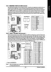
...GREEN_USB connector provides no standby power when system is shut down the standby power(note) for their USB devices during system power-off. - 25 - GA-8I945G Pro 2 10 1 9 GA-8I945G 2 10 1 9 Pin No. 1 2 3 4 5 6 7 8 9 10 Definition Power Power USB DXUSB DyUSB DX+ USB Dy+ ... cable and connector will make the device unable to work or even damage it . For optional IEEE1394 cable, please contact your local dealer. Only for GA-8I945G Pro. 2 F2_1394 1 F1_1394 2 1 Pin No. 1 2 3 4 5 6 7 8 9 10 16 15 10 9 Definition TPA2+ TPA2GND GND TPB2+ TPB2No Pin Power Power GND Pin No....
...GREEN_USB connector provides no standby power when system is shut down the standby power(note) for their USB devices during system power-off. - 25 - GA-8I945G Pro 2 10 1 9 GA-8I945G 2 10 1 9 Pin No. 1 2 3 4 5 6 7 8 9 10 Definition Power Power USB DXUSB DyUSB DX+ USB Dy+ ... cable and connector will make the device unable to work or even damage it . For optional IEEE1394 cable, please contact your local dealer. Only for GA-8I945G Pro. 2 F2_1394 1 F1_1394 2 1 Pin No. 1 2 3 4 5 6 7 8 9 10 16 15 10 9 Definition TPA2+ TPA2GND GND TPB2+ TPB2No Pin Power Power GND Pin No....

Manual
Page 26
... before you connect the COMA cable. Please contact your nearest dealer for the optional GIGABYTE external device. Pin No. Check the pin assignments while you connect the external device cable. Definition 1 Power 2 RFID_RI- 1 3 RF_TXD 4 RF_RXD 5 NC 6 GND GA-8I945G Pro/GA-8I945G Motherboard - 26 - Please contact your nearest dealer for optional COMA cable. 2 10 1 9 Pin No...
... before you connect the COMA cable. Please contact your nearest dealer for the optional GIGABYTE external device. Pin No. Check the pin assignments while you connect the external device cable. Definition 1 Power 2 RFID_RI- 1 3 RF_TXD 4 RF_RXD 5 NC 6 GND GA-8I945G Pro/GA-8I945G Motherboard - 26 - Please contact your nearest dealer for optional COMA cable. 2 10 1 9 Pin No...

Manual
Page 28
Dispose of explosion if battery is incorrectly replaced. GA-8I945G Pro/GA-8I945G Motherboard - 28 - Plug the power cord and turn ON the computer. Take out the battery gently and put it aside for one minute). 3. Turn OFF ...
Dispose of explosion if battery is incorrectly replaced. GA-8I945G Pro/GA-8I945G Motherboard - 28 - Plug the power cord and turn ON the computer. Take out the battery gently and put it aside for one minute). 3. Turn OFF ...
Manual
Page 30
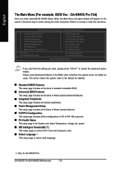
... the setting you enter Award BIOS CMOS Setup Utility, the Main Menu (as usual. This action makes the system reset to the default for GA-8I945G Pro. GA-8I945G Pro/GA-8I945G Motherboard - 30 - Only for stability. „ Standard CMOS Features This setup page includes all the items in the BIOS when somehow the ...system works not stable as figure below) will appear on the screen. English The Main Menu (For example: BIOS Ver. : GA-8I945G Pro F2d) Once you want, please press "Ctrl+F1" to search the advanced option hidden. Use arrow keys to select among the items and ...
... the setting you enter Award BIOS CMOS Setup Utility, the Main Menu (as usual. This action makes the system reset to the default for GA-8I945G Pro. GA-8I945G Pro/GA-8I945G Motherboard - 30 - Only for stability. „ Standard CMOS Features This setup page includes all the items in the BIOS when somehow the ...system works not stable as figure below) will appear on the screen. English The Main Menu (For example: BIOS Ver. : GA-8I945G Pro F2d) Once you want, please press "Ctrl+F1" to search the advanced option hidden. Use arrow keys to select among the items and ...
Manual
Page 32
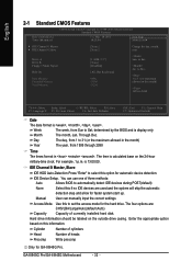
... ESC: Exit F1: General Help F7: Optimized Defaults Date The date format is calculated base on the outside drive casing. IDE Device Setup. GA-8I945G Pro/GA-8I945G Motherboard - 32 - is display only The month, Jan. IDE Channel 0 Master, Slave IDE HDD Auto-Detection Press "Enter" to automatically ...appropriate option based on this to Sat. The four options are used and the system will skip the automatic detection step and allow for GA-8I945G Pro. English 2-1 Standard CMOS Features Date (mm:dd:yy) Time (hh:mm:ss) CMOS Setup Utility-Copyright (C) 1984-2005 Award Software ...
... ESC: Exit F1: General Help F7: Optimized Defaults Date The date format is calculated base on the outside drive casing. IDE Device Setup. GA-8I945G Pro/GA-8I945G Motherboard - 32 - is display only The month, Jan. IDE Channel 0 Master, Slave IDE HDD Auto-Detection Press "Enter" to automatically ...appropriate option based on this to Sat. The four options are used and the system will skip the automatic detection step and allow for GA-8I945G Pro. English 2-1 Standard CMOS Features Date (mm:dd:yy) Time (hh:mm:ss) CMOS Setup Utility-Copyright (C) 1984-2005 Award Software ...
