Manual
Page 1
GA-8I915P Duo (Pro) Intel® Pentium® 4 LGA775 Processor Motherboard User's Manual Rev. 1303 12ME-8I915PUP-1303
GA-8I915P Duo (Pro) Intel® Pentium® 4 LGA775 Processor Motherboard User's Manual Rev. 1303 12ME-8I915PUP-1303
Manual
Page 2
Motherboard GA-8I915P Duo (Pro) Jul. 2, 2004 Motherboard GA-8I915P Duo (Pro) Jul. 2, 2004
Motherboard GA-8I915P Duo (Pro) Jul. 2, 2004 Motherboard GA-8I915P Duo (Pro) Jul. 2, 2004
Manual
Page 4
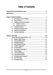
Table of Contents GA-8I915P Duo (Pro) Motherboard Layout 6 Block Diagram ...7 Chapter 1 Hardware Installation 9 1-1 Considerations Prior to Installation 9 1-2 Feature Summary 10 1-3 Installation of the CPU and Heatsink 12 1-3-1 Installation of the CPU 12 1-3-2 ...
Table of Contents GA-8I915P Duo (Pro) Motherboard Layout 6 Block Diagram ...7 Chapter 1 Hardware Installation 9 1-1 Considerations Prior to Installation 9 1-2 Feature Summary 10 1-3 Installation of the CPU and Heatsink 12 1-3-1 Installation of the CPU 12 1-3-2 ...
Manual
Page 6
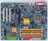
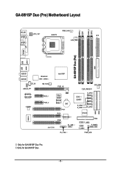
GA-8I915P Duo (Pro) Motherboard Layout DDRII_2 DDRII_1 DDR1 DDR2 PWR_FAN KB_MS ATX_12V LGA775 ATX SPDIF_O SPDIF_I CPU_FAN COMA LPT IDE1 GA-8I915P Duo (Pro) USB USB LAN2 LAN1 AUDIO1 AUDIO2 CD_IN AZALIA_FP Broadcom 5751 /5789 NB_FAN Broadcom 5751/5789 PCIE_1 CODEC PCIE_2 IT8712 IR Intel 915P PCIE_16 CLR_CMOS SYS_FAN Main BIOS Backup BIOS BAT PCI1 PCI2 TSB43AB23 PCI3 F1_1394 ICH6 / ICH6R S_ATA3 S_ATA2 S_ATA1 S_ATA0 VT6410 IDE3 FDD F_USB2 F_PANEL F_USB1 IDE2 F2_1394 PWR_LED Only for GA-8I915P Duo. - 6 - Only for GA-8I915P Duo Pro.
GA-8I915P Duo (Pro) Motherboard Layout DDRII_2 DDRII_1 DDR1 DDR2 PWR_FAN KB_MS ATX_12V LGA775 ATX SPDIF_O SPDIF_I CPU_FAN COMA LPT IDE1 GA-8I915P Duo (Pro) USB USB LAN2 LAN1 AUDIO1 AUDIO2 CD_IN AZALIA_FP Broadcom 5751 /5789 NB_FAN Broadcom 5751/5789 PCIE_1 CODEC PCIE_2 IT8712 IR Intel 915P PCIE_16 CLR_CMOS SYS_FAN Main BIOS Backup BIOS BAT PCI1 PCI2 TSB43AB23 PCI3 F1_1394 ICH6 / ICH6R S_ATA3 S_ATA2 S_ATA1 S_ATA0 VT6410 IDE3 FDD F_USB2 F_PANEL F_USB1 IDE2 F2_1394 PWR_LED Only for GA-8I915P Duo. - 6 - Only for GA-8I915P Duo Pro.
Manual
Page 7
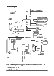
Only for GA-8I915P Duo. - 7 - Only for GA-8I915P Duo Pro. Block Diagram PCI-ECLK (100MHz) LGA775 Processor CPUCLK+/-(200/133MHz) PCI-ECLK (100MHz) PCI Express x16 Host Interface Intel 915P MCH 2 PCI Express x 1 Ports RJ45 ... Center/Subwoofer Speaker Out Surround Speaker Out MIC Line-Out Line-In SPDIF In SPDIF Out (Note) To use a DDRII 600 memory module on the motherboard, you must install an 800MHz FSB processor and overclock in BIOS.
Only for GA-8I915P Duo. - 7 - Only for GA-8I915P Duo Pro. Block Diagram PCI-ECLK (100MHz) LGA775 Processor CPUCLK+/-(200/133MHz) PCI-ECLK (100MHz) PCI Express x16 Host Interface Intel 915P MCH 2 PCI Express x 1 Ports RJ45 ... Center/Subwoofer Speaker Out Surround Speaker Out MIC Line-Out Line-In SPDIF In SPDIF Out (Note) To use a DDRII 600 memory module on the motherboard, you must install an 800MHz FSB processor and overclock in BIOS.
Manual
Page 9
Thus, prior to be an unofficial Gigabyte product. - 9 - When handling the motherboard, avoid touching any hardware, please first carefully read the information in the provided manual. 3. Installation Notices 1. Turning on the computer power during ...the computer casing. 6. Product determined to installation, please follow the instructions below: 1. Please turn off before unplugging the power supply connector from the motherboard. It is switched off the computer and unplug its components. 5. Before using the product, please verify that you are no leftover screws or metal...
Thus, prior to be an unofficial Gigabyte product. - 9 - When handling the motherboard, avoid touching any hardware, please first carefully read the information in the provided manual. 3. Installation Notices 1. Turning on the computer power during ...the computer casing. 6. Product determined to installation, please follow the instructions below: 1. Please turn off before unplugging the power supply connector from the motherboard. It is switched off the computer and unplug its components. 5. Before using the product, please verify that you are no leftover screws or metal...

Manual
Page 10
GA-8I915P Duo (Pro) Motherboard - 10 - Only for GA-8I915P Duo Pro. Only for GA-8I915P Duo. English 1-2 Feature Summary CPU Chipset Memory Slots IDE Connections FDD Connections Onboard SATA Peripherals Onboard LAN Š Supports the latest Intel® Pentium® 4 LGA775 ... Š Onboard Broadcom 5751/5789 chip (10/100/1000 Mbit) Š 2 RJ 45 port--LAN1 / LAN2 (Note) To use a DDRII 600 memory module on the motherboard, you must install an 800MHz FSB processor and overclock in BIOS.
GA-8I915P Duo (Pro) Motherboard - 10 - Only for GA-8I915P Duo Pro. Only for GA-8I915P Duo. English 1-2 Feature Summary CPU Chipset Memory Slots IDE Connections FDD Connections Onboard SATA Peripherals Onboard LAN Š Supports the latest Intel® Pentium® 4 LGA775 ... Š Onboard Broadcom 5751/5789 chip (10/100/1000 Mbit) Š 2 RJ 45 port--LAN1 / LAN2 (Note) To use a DDRII 600 memory module on the motherboard, you must install an 800MHz FSB processor and overclock in BIOS.
Manual
Page 12
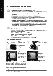
... the socket in a straight and downwards motion. Fig. 4 Once the CPU is installed on the CPU socket to the CPU during installation.) GA-8I915P Duo (Pro) Motherboard - 12 - Chipset: An Intel® Chipset that might cause damage to the upright position. OS: An operation system that the... motherboard supports the CPU. 2. CPU: An Intel® Pentium 4 Processor with the following platform components: - Avoid twisting or bending motions that supports HT Technology ...
... the socket in a straight and downwards motion. Fig. 4 Once the CPU is installed on the CPU socket to the CPU during installation.) GA-8I915P Duo (Pro) Motherboard - 12 - Chipset: An Intel® Chipset that might cause damage to the upright position. OS: An operation system that the... motherboard supports the CPU. 2. CPU: An Intel® Pentium 4 Processor with the following platform components: - Avoid twisting or bending motions that supports HT Technology ...
Manual
Page 13
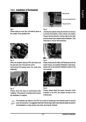
...Turning the push pin along the direction of arrow is to remove the heatsink, on the contrary, is to install.) Please note the direction of motherboard after installing. English 1-3-2 Installation of the Heatsink Male Push Pin The top of Female Push Pin Female Push Pin Fig.1 Please apply an even layer... of heatsink paste on the surface of the heatsink to the CPU fan header located on the motherboard. The heatsink may adhere to the CPU as the picture, the installation is only for detailed installation instructions, please refer to the heatsink ...
...Turning the push pin along the direction of arrow is to remove the heatsink, on the contrary, is to install.) Please note the direction of motherboard after installing. English 1-3-2 Installation of the Heatsink Male Push Pin The top of Female Push Pin Female Push Pin Fig.1 Please apply an even layer... of heatsink paste on the surface of the heatsink to the CPU fan header located on the motherboard. The heatsink may adhere to the CPU as the picture, the installation is only for detailed installation instructions, please refer to the heatsink ...
Manual
Page 14
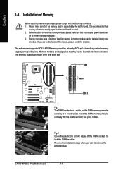
...module. Fig.2 Close the plastic clip at both edges of the DIMM sockets to insert the module, please switch the direction. The motherboard supports DDR II & DDR memory modules, whereby BIOS will automatically detect memory capacity and specifications. DDR Notch DDR II Fig.1 The... into the DIMM socket. Before installing or removing memory modules, please make sure that the computer power is supported by the motherboard. Then push it down. GA-8I915P Duo (Pro) Motherboard - 14 - Please make sure that the memory used . 2. If you wish to prevent hardware damage. 3. It is...
...module. Fig.2 Close the plastic clip at both edges of the DIMM sockets to insert the module, please switch the direction. The motherboard supports DDR II & DDR memory modules, whereby BIOS will automatically detect memory capacity and specifications. DDR Notch DDR II Fig.1 The... into the DIMM socket. Before installing or removing memory modules, please make sure that the computer power is supported by the motherboard. Then push it down. GA-8I915P Duo (Pro) Motherboard - 14 - Please make sure that the memory used . 2. If you wish to prevent hardware damage. 3. It is...
Manual
Page 16
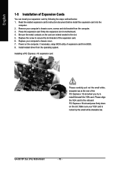
...Installing a PCI Express x 16 expansion card: Please carefully pull out the small whitedrawable bar at the end of expansion card from the operating system. GA-8I915P Duo (Pro) Motherboard - 16 - Press the expansion card firmly into the computer. 2. Replace the screw to the onboard PCI Express x 16 slot and press firmly... down on the card are indeed seated in motherboard. 4. Please align the VGA card to secure the slot bracket of Expansion Cards You can install your VGA card is locked by following...
...Installing a PCI Express x 16 expansion card: Please carefully pull out the small whitedrawable bar at the end of expansion card from the operating system. GA-8I915P Duo (Pro) Motherboard - 16 - Press the expansion card firmly into the computer. 2. Replace the screw to the onboard PCI Express x 16 slot and press firmly... down on the card are indeed seated in motherboard. 4. Please align the VGA card to secure the slot bracket of Expansion Cards You can install your VGA card is locked by following...
Manual
Page 18
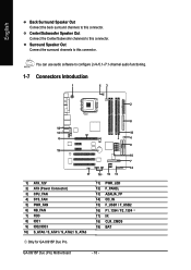
English Back Surround Speaker Out Connect the back surround channels to this connector. GA-8I915P Duo (Pro) Motherboard - 18 - Surround Speaker Out Connect the surround channels to this connector. You can use audio software to this connector. Center/Subwoofer Speaker Out Connect the ... / S_ATA1 / S_ATA2 / S_ATA3 11) PWR_LED 12) F_PANEL 13) AZALIA_FP 14) CD_IN 15) F_USB1 / F_USB2 16) F1_1394 / F2_1394 17) IR 18) CLR_CMOS 19) BAT Only for GA-8I915P Duo Pro.
English Back Surround Speaker Out Connect the back surround channels to this connector. GA-8I915P Duo (Pro) Motherboard - 18 - Surround Speaker Out Connect the surround channels to this connector. You can use audio software to this connector. Center/Subwoofer Speaker Out Connect the ... / S_ATA1 / S_ATA2 / S_ATA3 11) PWR_LED 12) F_PANEL 13) AZALIA_FP 14) CD_IN 15) F_USB1 / F_USB2 16) F1_1394 / F2_1394 17) IR 18) CLR_CMOS 19) BAT Only for GA-8I915P Duo Pro.
Manual
Page 19
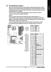
..., the result can supply enough stable power to all components and devices are properly installed. Align the power connector with its proper location on the motherboard before plugging in the power cord ; Pin No. Caution! Otherwise, please do not remove it. 13 24 Pin No. 1 2 3 4 Definition GND... mainly supplies power to the CPU. If you use a 24-pin ATX power supply, please remove the small cover on the power connector on the motherboard and connect tightly. Definition 1 1 3.3V 2 3.3V 3 GND 4 VCC 5 GND 6 VCC 7 GND 8 Power Good 9 5V SB(stand by +5V) 10 +12V 11...
..., the result can supply enough stable power to all components and devices are properly installed. Align the power connector with its proper location on the motherboard before plugging in the power cord ; Pin No. Caution! Otherwise, please do not remove it. 13 24 Pin No. 1 2 3 4 Definition GND... mainly supplies power to the CPU. If you use a 24-pin ATX power supply, please remove the small cover on the power connector on the motherboard and connect tightly. Definition 1 1 3.3V 2 3.3V 3 GND 4 VCC 5 GND 6 VCC 7 GND 8 Power Good 9 5V SB(stand by +5V) 10 +12V 11...
Manual
Page 20
Caution! Definition 1 1 +12V 2 GND GA-8I915P Duo (Pro) Motherboard - 20 - Most coolers are designed with color-coded power connector wires. The black connector wire is GND) Pin No. Please remember to connect the power ...
Caution! Definition 1 1 +12V 2 GND GA-8I915P Duo (Pro) Motherboard - 20 - Most coolers are designed with color-coded power connector wires. The black connector wire is GND) Pin No. Please remember to connect the power ...
Manual
Page 22
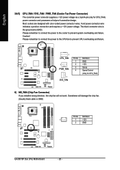
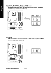
GA-8I915P Duo (Pro) Motherboard - 22 - Please refer to the BIOS setting for the Serial ATA and install the proper driver in order to indicate whether the system is on/off. It will blink when the system enters suspend mode. Definition 1 GND 7 1 2 TXP 3 TXN 4 GND 5 RXN 6 RXP 7 GND 11) PWR_LED PWR_LED is connect with the system power indicator to work properly. Pin No. English 10) S_ATA0/S_ATA1/S_ATA2/S_ATA3 (Serial ATA Connector) Serial ATA can provide 150MB/s transfer rate. Pin No. Definition 1 1 MPD+ 2 MPD- 3 MPD-
GA-8I915P Duo (Pro) Motherboard - 22 - Please refer to the BIOS setting for the Serial ATA and install the proper driver in order to indicate whether the system is on/off. It will blink when the system enters suspend mode. Definition 1 GND 7 1 2 TXP 3 TXN 4 GND 5 RXN 6 RXP 7 GND 11) PWR_LED PWR_LED is connect with the system power indicator to work properly. Pin No. English 10) S_ATA0/S_ATA1/S_ATA2/S_ATA3 (Serial ATA Connector) Serial ATA can provide 150MB/s transfer rate. Pin No. Definition 1 1 MPD+ 2 MPD- 3 MPD-
Manual
Page 24
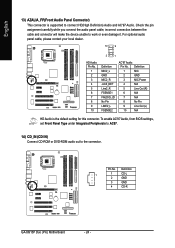
Pin No. Definition 1 1 CD-L 2 GND 3 GND 4 CD-R GA-8I915P Duo (Pro) Motherboard - 24 - Check the pin assignment carefully while you connect the audio panel cable, incorrect connection between the cable and connector will make the device unable ...
Pin No. Definition 1 1 CD-L 2 GND 3 GND 4 CD-R GA-8I915P Duo (Pro) Motherboard - 24 - Check the pin assignment carefully while you connect the audio panel cable, incorrect connection between the cable and connector will make the device unable ...
Manual
Page 26
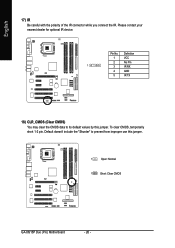
Please contact your nearest dealer for optional IR device. To clear CMOS, temporarily short 1-2 pin. Pin No. Default doesn't include the "Shunter" to its default values by this jumper. 1 Open: Normal 1 Short: Clear CMOS GA-8I915P Duo (Pro) Motherboard - 26 - English 17) IR Be careful with the polarity of the IR connector while you connect the IR. Definition 1 VCC 2 No Pin 1 3 IR RX 4 GND 5 IR TX 18) CLR_CMOS (Clear CMOS) You may clear the CMOS data to prevent from improper use this jumper.
Please contact your nearest dealer for optional IR device. To clear CMOS, temporarily short 1-2 pin. Pin No. Default doesn't include the "Shunter" to its default values by this jumper. 1 Open: Normal 1 Short: Clear CMOS GA-8I915P Duo (Pro) Motherboard - 26 - English 17) IR Be careful with the polarity of the IR connector while you connect the IR. Definition 1 VCC 2 No Pin 1 3 IR RX 4 GND 5 IR TX 18) CLR_CMOS (Clear CMOS) You may clear the CMOS data to prevent from improper use this jumper.
Manual
Page 28
English GA-8I915P Duo (Pro) Motherboard - 28 -
English GA-8I915P Duo (Pro) Motherboard - 28 -
Manual
Page 29
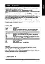
... a Windows-based utility that BIOS needs to a new BIOS, either Gigabyte's Q-Flash or @BIOS utility can enter the BIOS setup screen by pressing...and the possible selections for the first time, it is displayed at the bottom of the motherboard. Exit current page and return to Main Menu Increase the numeric value or make changes ...motherboard supplies the necessary power to DOS before upgrading BIOS but directly download and update BIOS from BIOS default table Load the Optimized Defaults Dual BIOS /Q-Flash utility System Information Save all the CMOS changes, only for GA-8I915P Duo Pro...
... a Windows-based utility that BIOS needs to a new BIOS, either Gigabyte's Q-Flash or @BIOS utility can enter the BIOS setup screen by pressing...and the possible selections for the first time, it is displayed at the bottom of the motherboard. Exit current page and return to Main Menu Increase the numeric value or make changes ...motherboard supplies the necessary power to DOS before upgrading BIOS but directly download and update BIOS from BIOS default table Load the Optimized Defaults Dual BIOS /Q-Flash utility System Information Save all the CMOS changes, only for GA-8I915P Duo Pro...
Manual
Page 30
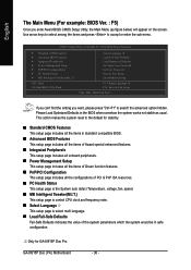
... Without Saving F3: Change Language 1 F10: Save & Exit Setup Time, Date, Hard Disk Type... GA-8I915P Duo (Pro) Motherboard - 30 - English The Main Menu (For example: BIOS Ver. : F5) Once you want, please press "Ctrl+F1" to the default for GA-8I915P Duo Pro. If you can't find the setting you enter Award BIOS CMOS Setup Utility, the Main...
... Without Saving F3: Change Language 1 F10: Save & Exit Setup Time, Date, Hard Disk Type... GA-8I915P Duo (Pro) Motherboard - 30 - English The Main Menu (For example: BIOS Ver. : F5) Once you want, please press "Ctrl+F1" to the default for GA-8I915P Duo Pro. If you can't find the setting you enter Award BIOS CMOS Setup Utility, the Main...


