Manual
Page 1
GA-8I915P-D Pro Intel® Pentium® 4 LGA775 Processor Motherboard User's Manual Rev. 2003 12ME-8I915PDP-2003
GA-8I915P-D Pro Intel® Pentium® 4 LGA775 Processor Motherboard User's Manual Rev. 2003 12ME-8I915PDP-2003

Manual
Page 2
Motherboard GA-8I915P-D Pro Jun. 11, 2004 Motherboard GA-8I915P-D Pro Jun. 11, 2004
Motherboard GA-8I915P-D Pro Jun. 11, 2004 Motherboard GA-8I915P-D Pro Jun. 11, 2004

Manual
Page 3
... Ma nual". The trademarks mentioned in the following: n For quick installation, please refer to assist in the use of Gigabyte. Notice The written co ntent provided with the product. Specifications and features are legally registered to their respective companies. n ...All rights reserved. For more productdetails, please click onto Gigabyte's website at www.gigabyte.com.tw n For detailed information related to Gigabyte's unique features, please go to "Technology Guide" section on Gigabyte's website to chang e without Gigabyte's prior written permission. Copyright © 2004 GIGA-...
... Ma nual". The trademarks mentioned in the following: n For quick installation, please refer to assist in the use of Gigabyte. Notice The written co ntent provided with the product. Specifications and features are legally registered to their respective companies. n ...All rights reserved. For more productdetails, please click onto Gigabyte's website at www.gigabyte.com.tw n For detailed information related to Gigabyte's unique features, please go to "Technology Guide" section on Gigabyte's website to chang e without Gigabyte's prior written permission. Copyright © 2004 GIGA-...

Manual
Page 4
Table of Contents GA-8I915P-D Pro Motherboard Layout 6 Block Diagram ...7 Chapter 1 Hardware Installation 9 1-1 Considerations Prior to Installation 9 1-2 Feature Summary 10 1-3 Installation of the CPU and Heatsink 12 1-3-1 Installation of the CPU ...
Table of Contents GA-8I915P-D Pro Motherboard Layout 6 Block Diagram ...7 Chapter 1 Hardware Installation 9 1-1 Considerations Prior to Installation 9 1-2 Feature Summary 10 1-3 Installation of the CPU and Heatsink 12 1-3-1 Installation of the CPU ...
Manual
Page 5
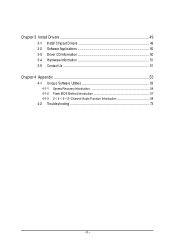
Chapter 3 Install Drivers 49 3-1 Install Chipset Drivers 49 3-2 Software Applications 50 3-3 Driver CD Information 50 3-4 Hardware Information 51 3-5 Contact Us ...51 Chapter 4 Appendix 53 4-1 Unique Software Utilities 53 4-1-1 Xpress Recovery Introduction 54 4-1-2 Flash BIOS Method Introduction 57 4-1-3 2- / 4- / 6- / 8- Channel Audio Function Introduction 68 4-2 Troubleshooting 73 - 5 -
Chapter 3 Install Drivers 49 3-1 Install Chipset Drivers 49 3-2 Software Applications 50 3-3 Driver CD Information 50 3-4 Hardware Information 51 3-5 Contact Us ...51 Chapter 4 Appendix 53 4-1 Unique Software Utilities 53 4-1-1 Xpress Recovery Introduction 54 4-1-2 Flash BIOS Method Introduction 57 4-1-3 2- / 4- / 6- / 8- Channel Audio Function Introduction 68 4-2 Troubleshooting 73 - 5 -
Manual
Page 7
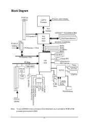
Block Diagram PCI-ECLK (100M Hz) LGA775 Processor CPUCLK+/-(200/133M Hz) Ho st Interfa ce DDRII 600(Note)/533/400MHz DIMM PCI-ECLK (100M Hz) PCI Express x16 In te l 915P MCH 3 PCI Express x 1 Ports Dual Channel Memory MCHCLK (133/200MHz) 66MHz 33MHz 14.318M Hz 48MHz PCI Express x1 Bus PCI Bus TSB43 AB23 M arvell 8001 Dual BIOS 4 Serial ATA In te l ICH6 ATA33/66/100 IDE Channels Floppy IT 8712 LPT Port RJ45 CODEC COM Port 24MHz 8 USB 33MHz Ports 2 PCI PS/2 KB/Mouse 3 IEEE1394 Surround Speaker Out Center/Subwoofer Speaker Out Side Speaker Out MIC Line-Out Line-In SPDIF...
Block Diagram PCI-ECLK (100M Hz) LGA775 Processor CPUCLK+/-(200/133M Hz) Ho st Interfa ce DDRII 600(Note)/533/400MHz DIMM PCI-ECLK (100M Hz) PCI Express x16 In te l 915P MCH 3 PCI Express x 1 Ports Dual Channel Memory MCHCLK (133/200MHz) 66MHz 33MHz 14.318M Hz 48MHz PCI Express x1 Bus PCI Bus TSB43 AB23 M arvell 8001 Dual BIOS 4 Serial ATA In te l ICH6 ATA33/66/100 IDE Channels Floppy IT 8712 LPT Port RJ45 CODEC COM Port 24MHz 8 USB 33MHz Ports 2 PCI PS/2 KB/Mouse 3 IEEE1394 Surround Speaker Out Center/Subwoofer Speaker Out Side Speaker Out MIC Line-Out Line-In SPDIF...
Manual
Page 9
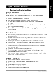
... the motherboard. To prevent damage to the motherboard, please do not allow screws to come in the provided manual. 3. Damage due to be an unofficial Gigabyte product. - 9 - Product determined to natural disaster, accident or human cause. 2. Prior to installation, please do not place the computer system on top of electrostatic discharge...
... the motherboard. To prevent damage to the motherboard, please do not allow screws to come in the provided manual. 3. Damage due to be an unofficial Gigabyte product. - 9 - Product determined to natural disaster, accident or human cause. 2. Prior to installation, please do not place the computer system on top of electrostatic discharge...

Manual
Page 10
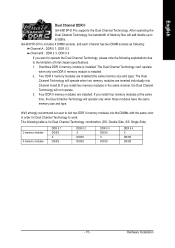
.... (Note 2) To use a DDRII 600 memory module on the motherboard, you must install an 800MHz FSB processor and overclock in BIOS. Center/Subwoofer Speaker Out ; GA-8I915P-D Pro Motherboard - 10 - Line Out (Front Speaker Out) ; Surround Speaker Out (Rear Speaker Out) ; MIC ;
.... (Note 2) To use a DDRII 600 memory module on the motherboard, you must install an 800MHz FSB processor and overclock in BIOS. Center/Subwoofer Speaker Out ; GA-8I915P-D Pro Motherboard - 10 - Line Out (Front Speaker Out) ; Surround Speaker Out (Rear Speaker Out) ; MIC ;

Manual
Page 11
Hardware Installation English Hardware Monitor BIOS Additional Features Overclocking Form Factor w System voltage detection w CPU temperature detection w CPU / System / Power fan speed detection w CPU warning temperature w CPU / System / Power fan failure warning w CPU smart fan control w Use of licensed AWARD BIOS w Supports Dual BIOS/Q-Flash/Multilanguage w Supports @BIOS w Supports EasyTune w Over Voltage via BIOS (CPU/DDR II/PCI-E) w Over Clock via BIOS (CPU/DDR II) w ATX form factor; 30.5cm x 24.4cm - 11 -
Hardware Installation English Hardware Monitor BIOS Additional Features Overclocking Form Factor w System voltage detection w CPU temperature detection w CPU / System / Power fan speed detection w CPU warning temperature w CPU / System / Power fan failure warning w CPU smart fan control w Use of licensed AWARD BIOS w Supports Dual BIOS/Q-Flash/Multilanguage w Supports @BIOS w Supports EasyTune w Over Voltage via BIOS (CPU/DDR II/PCI-E) w Over Clock via BIOS (CPU/DDR II) w ATX form factor; 30.5cm x 24.4cm - 11 -

Manual
Page 12
... Technology - Fig. 2 Remove the plastic covering on the CPU socket to set beyond the proper specifications, please do so according to the CPU during installation.) GA-8I915P-D Pro Motherboard - 12 - Please make sure the heatsink is installed on the edge of the CPU socket. Chipset: An Intel® Chipset that might cause damage...
... Technology - Fig. 2 Remove the plastic covering on the CPU socket to set beyond the proper specifications, please do so according to the CPU during installation.) GA-8I915P-D Pro Motherboard - 12 - Please make sure the heatsink is installed on the edge of the CPU socket. Chipset: An Intel® Chipset that might cause damage...
Manual
Page 13
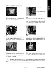
Fig. 2 (Turning the push pin along the direction of arrow is to remove the heatsink, on the contrary, is to install.) Please note the direction of motherboard after installing. Hardware Installation Fig. 4 Please make sure the push pins aim to the pin hole on the motherboard.Pressing down the push pins diagonally. The heatsink may adhere to the CPU as the picture, the installation is complete. English 1-3-2 Installation of the Heatsink Male Push Pin The top of Female Push Pin Female Push Pin Fig.1 Please apply an even layer of heatsink paste on the surface of the heatsink to ...
Fig. 2 (Turning the push pin along the direction of arrow is to remove the heatsink, on the contrary, is to install.) Please note the direction of motherboard after installing. Hardware Installation Fig. 4 Please make sure the push pins aim to the pin hole on the motherboard.Pressing down the push pins diagonally. The heatsink may adhere to the CPU as the picture, the installation is complete. English 1-3-2 Installation of the Heatsink Male Push Pin The top of Female Push Pin Female Push Pin Fig.1 Please apply an even layer of heatsink paste on the surface of the heatsink to ...
Manual
Page 14
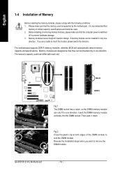
..., please comply with each slot. Notch DDR II Fig.1 The DIMM socket has a notch, so the DIMM memory module can be installed in one direction. GA-8I915P-D Pro Motherboard - 14 -
..., please comply with each slot. Notch DDR II Fig.1 The DIMM socket has a notch, so the DIMM memory module can be installed in one direction. GA-8I915P-D Pro Motherboard - 14 -
Manual
Page 15
... install four memory modules at the same time, the Dual Channel Technology will operate only when those modules have the same memory size and type. GA-8I915P-D Pro includes 4 DIMM sockets, and each Channel has two DIMM sockets as following: Channel A : DDR II 1, DDR II 2 Channel B : ...will not operate. 3. After operating the Dual Channel Technology, the bandwidth of Intel chipset specifications. 1. English Dual Channel DDR II GA-8I915P-D Pro supports the Dual Channel Technology. Four DDR II memory modules are inserted individually into the DIMMs with the same color in the same...
... install four memory modules at the same time, the Dual Channel Technology will operate only when those modules have the same memory size and type. GA-8I915P-D Pro includes 4 DIMM sockets, and each Channel has two DIMM sockets as following: Channel A : DDR II 1, DDR II 2 Channel B : ...will not operate. 3. After operating the Dual Channel Technology, the bandwidth of Intel chipset specifications. 1. English Dual Channel DDR II GA-8I915P-D Pro supports the Dual Channel Technology. Four DDR II memory modules are inserted individually into the DIMMs with the same color in the same...
Manual
Page 16
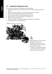
... can install your VGA card is locked by following the steps outlined below: 1. Replace the screw to secure the slot bracket of the expansion card. 6. GA-8I915P-D Pro Motherboard - 16 -
... can install your VGA card is locked by following the steps outlined below: 1. Replace the screw to secure the slot bracket of the expansion card. 6. GA-8I915P-D Pro Motherboard - 16 -

Manual
Page 17
SPDIF_I (SPDIF In) Use SPDIF In feature only when your OS does not support USB controller, please contact OS vendor for possible patch or driver upgrade. have a standard USB interface. LAN Port The provided Internet connection is capable of providing digital audio to external speakers or compressed AC3 data to Line In jack. can be connected to an external Dolby Digital Decoder. Hardware Installation If your device has digital output function. For more information please contact your OS supports USB controller. Also make sure your device(s) such as USB keyboard, mouse, scanner,...
SPDIF_I (SPDIF In) Use SPDIF In feature only when your OS does not support USB controller, please contact OS vendor for possible patch or driver upgrade. have a standard USB interface. LAN Port The provided Internet connection is capable of providing digital audio to external speakers or compressed AC3 data to Line In jack. can be connected to an external Dolby Digital Decoder. Hardware Installation If your device has digital output function. For more information please contact your OS supports USB controller. Also make sure your device(s) such as USB keyboard, mouse, scanner,...

Manual
Page 18
... 8) IDE 9) S_ATA0 / S_ATA1 / S_ATA2 / S_ATA3 10) PWR_LED 11) F_PANEL 12) AZALIA_FP 13) CD_IN 14) F_USB1 / F_USB2 15) F1_1394 / F2_1394 16) IR 17) CLR_CMOS 18) BAT GA-8I915P-D Pro Motherboard - 18 - You can use audio software to this connector. Side Speaker Out Connect the side surround speakers to this connector.
... 8) IDE 9) S_ATA0 / S_ATA1 / S_ATA2 / S_ATA3 10) PWR_LED 11) F_PANEL 12) AZALIA_FP 13) CD_IN 14) F_USB1 / F_USB2 15) F1_1394 / F2_1394 16) IR 17) CLR_CMOS 18) BAT GA-8I915P-D Pro Motherboard - 18 - You can use audio software to this connector. Side Speaker Out Connect the side surround speakers to this connector.
Manual
Page 19
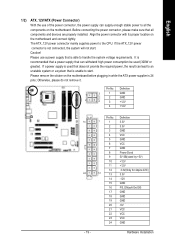
If a power supply is used (300W or greater). Pin No. Caution! Please remove the sticker on the motherboard and connect tightly. Pin No. The ATX_12V power connector mainly supplies power to all components and devices are properly installed. It is recommended that a power supply that can lead to an unstable system or a system that does not provide the required power, the result can withstand high power consumption be used that is 24 pins; Otherwise, please do not remove it. Definition 1 3 1 GND 2 GND 2 4 3 +12V 4 +12V 13 24 - 19 - Align the power ...
If a power supply is used (300W or greater). Pin No. Caution! Please remove the sticker on the motherboard and connect tightly. Pin No. The ATX_12V power connector mainly supplies power to all components and devices are properly installed. It is recommended that a power supply that can lead to an unstable system or a system that does not provide the required power, the result can withstand high power consumption be used that is 24 pins; Otherwise, please do not remove it. Definition 1 3 1 GND 2 GND 2 4 3 +12V 4 +12V 13 24 - 19 - Align the power ...

Manual
Page 20
... connector wires. Please remember to connect the power to the CPU fan to prevent system overheating and failure. Sometimes will not work. Definition 1 +12V 2 GND 1 GA-8I915P-D Pro Motherboard - 20 - Please remember to connect the power to the cooler to prevent CPU overheating and failure. 1 CPU_FAN 1 PWR_FAN 1 SYS_FAN Pin No. 1 2 3 4 Definition GND +12V...
... connector wires. Please remember to connect the power to the CPU fan to prevent system overheating and failure. Sometimes will not work. Definition 1 +12V 2 GND 1 GA-8I915P-D Pro Motherboard - 20 - Please remember to connect the power to the cooler to prevent CPU overheating and failure. 1 CPU_FAN 1 PWR_FAN 1 SYS_FAN Pin No. 1 2 3 4 Definition GND +12V...

Manual
Page 21
The types of the cable connects to the FDD drive. One IDE connector can then connect to two IDE devices (hard drive or optical drive). Please connect the red power connector wire to the pin1 position. 34 33 2 1 8) IDE (IDE Connector) An IDE device connects to the instructions located on the IDE device). 40 39 2 1 - 21 - Hardware Installation English 7) FDD (Floppy Connector) The FDD connector is used to connect the FDD cable while the other as Slave (for information on settings, please refer to the computer via an IDE connector. If you wish to connect two IDE devices, ...
The types of the cable connects to the FDD drive. One IDE connector can then connect to two IDE devices (hard drive or optical drive). Please connect the red power connector wire to the pin1 position. 34 33 2 1 8) IDE (IDE Connector) An IDE device connects to the instructions located on the IDE device). 40 39 2 1 - 21 - Hardware Installation English 7) FDD (Floppy Connector) The FDD connector is used to connect the FDD cable while the other as Slave (for information on settings, please refer to the computer via an IDE connector. If you wish to connect two IDE devices, ...

Manual
Page 22
English 9) S_ATA0/S_ATA1/S_ATA2/S_ATA3 (Serial ATA Connector, Controlled by ICH6) Serial ATA can provide 150MB/s transfer rate. It will blink when the system enters suspend mode. GA-8I915P-D Pro Motherboard - 22 - Pin No. Pin No. Definition 1 GND 1 7 2 TXP 3 TXN 4 GND 5 RXN 6 RXP 7 GND 10) PWR_LED PWR_LED is on/off. Definition 1 1 MPD+ 2 MPD- 3 MPD- Please refer to the BIOS setting for the Serial ATA and install the proper driver in order to indicate whether the system is connect with the system power indicator to work properly.
English 9) S_ATA0/S_ATA1/S_ATA2/S_ATA3 (Serial ATA Connector, Controlled by ICH6) Serial ATA can provide 150MB/s transfer rate. It will blink when the system enters suspend mode. GA-8I915P-D Pro Motherboard - 22 - Pin No. Pin No. Definition 1 GND 1 7 2 TXP 3 TXN 4 GND 5 RXN 6 RXP 7 GND 10) PWR_LED PWR_LED is on/off. Definition 1 1 MPD+ 2 MPD- 3 MPD- Please refer to the BIOS setting for the Serial ATA and install the proper driver in order to indicate whether the system is connect with the system power indicator to work properly.