Manual
Page 6
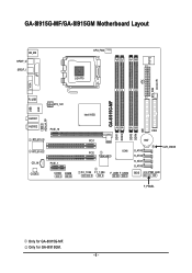
GA-8I915G-MF/GA-8I915GM Motherboard Layout IT8712 KB_MS SPDIF_O SPDIF_I CPU_FAN LGA775 SYS_FAN IR ATX VGA LPT R_USB ATX_12V USB LAN AZALIA_FP AUDIO1 AUDIO2 PCIE_16 RTL8110S RTL8100C CD_IN CODEC PCIE_1 COMA COMB GA-8I915G-MF DDR1 DDR2 Intel 915G IDE FDD DDR3 DDR4 PCI1 PCI2 ICH6 TSB43AB23 F2_1394 F1_1394 F_USB1 F_USB2 BAT S_ATA3 S_ATA2 S_ATA1 S_ATA0 CLR_CMOS BIOS PWR_LED F_PANEL Only for GA-8I915GM. - 6 - Only for GA-8I915G-MF.
GA-8I915G-MF/GA-8I915GM Motherboard Layout IT8712 KB_MS SPDIF_O SPDIF_I CPU_FAN LGA775 SYS_FAN IR ATX VGA LPT R_USB ATX_12V USB LAN AZALIA_FP AUDIO1 AUDIO2 PCIE_16 RTL8110S RTL8100C CD_IN CODEC PCIE_1 COMA COMB GA-8I915G-MF DDR1 DDR2 Intel 915G IDE FDD DDR3 DDR4 PCI1 PCI2 ICH6 TSB43AB23 F2_1394 F1_1394 F_USB1 F_USB2 BAT S_ATA3 S_ATA2 S_ATA1 S_ATA0 CLR_CMOS BIOS PWR_LED F_PANEL Only for GA-8I915GM. - 6 - Only for GA-8I915G-MF.
Manual
Page 10
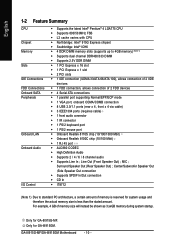
Only for GA-8I915G-MF. MIC ; Center/Subwoofer Speaker Out ;Side Speaker Out connection Š Supports SPDIF In/Out connection Š CD In Š IT8712 (Note 1) Due to 4GB memory) (... chip (10/100 Mbit) Š 1 RJ 45 port Š ALC880 CODEC Š High Definition Audio Š Supports 2 / 4 / 6 / 8 channel audio Š Supports Line In ; Only for GA-8I915GM. GA-8I915G-MF/GA-8I915GM Motherboard - 10 - Surround Speaker Out (Rear Speaker Out) ; For example, 4 GB of memory is reserved for system usage and therefore the actual memory size is less...
Only for GA-8I915G-MF. MIC ; Center/Subwoofer Speaker Out ;Side Speaker Out connection Š Supports SPDIF In/Out connection Š CD In Š IT8712 (Note 1) Due to 4GB memory) (... chip (10/100 Mbit) Š 1 RJ 45 port Š ALC880 CODEC Š High Definition Audio Š Supports 2 / 4 / 6 / 8 channel audio Š Supports Line In ; Only for GA-8I915GM. GA-8I915G-MF/GA-8I915GM Motherboard - 10 - Surround Speaker Out (Rear Speaker Out) ; For example, 4 GB of memory is reserved for system usage and therefore the actual memory size is less...
Manual
Page 12
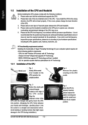
... metal lever back into its original position. Fig. 2 Remove the plastic covering on the CPU socket to the CPU during installation.) GA-8I915G-MF/GA-8I915GM Motherboard - 12 - Avoid twisting or bending motions that the system bus frequency be set beyond the proper specifications, please do so according...comply with HT Technology - If this occurs, please change the insert direction of the CPU socket. OS: An operation system that the motherboard supports the CPU. 2. If you wish to your hardware specifications including the CPU, graphics card, memory, hard drive, etc. Please ...
... metal lever back into its original position. Fig. 2 Remove the plastic covering on the CPU socket to the CPU during installation.) GA-8I915G-MF/GA-8I915GM Motherboard - 12 - Avoid twisting or bending motions that the system bus frequency be set beyond the proper specifications, please do so according...comply with HT Technology - If this occurs, please change the insert direction of the CPU socket. OS: An operation system that the motherboard supports the CPU. 2. If you wish to your hardware specifications including the CPU, graphics card, memory, hard drive, etc. Please ...
Manual
Page 14
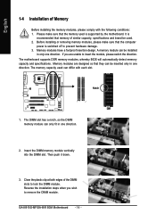
... you are designed so that the computer power is switched off to insert the module, please switch the direction. It is supported by the motherboard. GA-8I915G-MF/GA-8I915GM Motherboard - 14 - Memory modules have a foolproof insertion design. The memory capacity used is recommended that the memory used can only fit in one... with the following conditions: 1. Then push it down. 3. English 1-4 Installation of the DIMM slots to remove the DIMM module. The motherboard supports DDR memory modules, whereby BIOS will automatically detect memory capacity and specifications.
... you are designed so that the computer power is switched off to insert the module, please switch the direction. It is supported by the motherboard. GA-8I915G-MF/GA-8I915GM Motherboard - 14 - Memory modules have a foolproof insertion design. The memory capacity used is recommended that the memory used can only fit in one... with the following conditions: 1. Then push it down. 3. English 1-4 Installation of the DIMM slots to remove the DIMM module. The motherboard supports DDR memory modules, whereby BIOS will automatically detect memory capacity and specifications.
Manual
Page 16
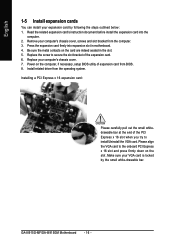
... driver from the computer. 3. Remove your computer's chassis cover, screws and slot bracket from the operating system. Power on the card are indeed seated in motherboard. 4. GA-8I915G-MF/GA-8I915GM Motherboard - 16 - Please align the VGA card to install/Uninstall the VGA card. English 1-5 Install expansion cards You can install your expansion card by the small...
... driver from the computer. 3. Remove your computer's chassis cover, screws and slot bracket from the operating system. Power on the card are indeed seated in motherboard. 4. GA-8I915G-MF/GA-8I915GM Motherboard - 16 - Please align the VGA card to install/Uninstall the VGA card. English 1-5 Install expansion cards You can install your expansion card by the small...
Manual
Page 18
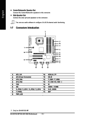
English Center/Subwoofer Speaker Out Connect the Center/Subwoofer speakers to this connector. GA-8I915G-MF/GA-8I915GM Motherboard - 18 - You can use audio software to this connector. Side Speaker Out Connect the side surround speakers to configure 2-/4-/6-/8-channel audio functioning. 1-7 Connectors Introduction 3 2 14 4 1 5 ...) F_USB1 / F_USB2 4) SYS_FAN 13) F1_1394 / F2_1394 5) FDD 14) IR 6) IDE 15) COMA / COMB 7) S_ATA0 / S_ATA1 / S_ATA2 / S_ATA3 16) CLR_CMOS 8) F_PANEL 17) BAT 9) PWR_LED Only for GA-8I915G-MF.
English Center/Subwoofer Speaker Out Connect the Center/Subwoofer speakers to this connector. GA-8I915G-MF/GA-8I915GM Motherboard - 18 - You can use audio software to this connector. Side Speaker Out Connect the side surround speakers to configure 2-/4-/6-/8-channel audio functioning. 1-7 Connectors Introduction 3 2 14 4 1 5 ...) F_USB1 / F_USB2 4) SYS_FAN 13) F1_1394 / F2_1394 5) FDD 14) IR 6) IDE 15) COMA / COMB 7) S_ATA0 / S_ATA1 / S_ATA2 / S_ATA3 16) CLR_CMOS 8) F_PANEL 17) BAT 9) PWR_LED Only for GA-8I915G-MF.
Manual
Page 20
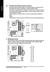
... connection design. Please connect the red power connector wire to the FDD drive. The types of the cable connects to the pin1 position. 34 33 2 1 GA-8I915G-MF/GA-8I915GM Motherboard - 20 - English 3/4) CPU_FAN / SYS_FAN (Cooler Fan Power Connector) The cooler fan power connector supplies a +12V power voltage via a 3-pin/4-pin (only for CPU_FAN) 5) FDD (Floppy...
... connection design. Please connect the red power connector wire to the FDD drive. The types of the cable connects to the pin1 position. 34 33 2 1 GA-8I915G-MF/GA-8I915GM Motherboard - 20 - English 3/4) CPU_FAN / SYS_FAN (Cooler Fan Power Connector) The cooler fan power connector supplies a +12V power voltage via a 3-pin/4-pin (only for CPU_FAN) 5) FDD (Floppy...
Manual
Page 22
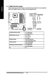
...- Pin 3: NC Pin 4: Data(-) Open: Normal Operation Close: Reset Hardware System Open: Normal Operation Close: Power On/Off Pin 1: LED anode(+) Pin 2: LED cathode(-) NC GA-8I915G-MF/GA-8I915GM Motherboard - 22 - English 8) F_PANEL (Front Panel Jumper) Please connect the power LED, PC peaker, reset switch and power switch etc of your chassis front panel to...
...- Pin 3: NC Pin 4: Data(-) Open: Normal Operation Close: Reset Hardware System Open: Normal Operation Close: Power On/Off Pin 1: LED anode(+) Pin 2: LED cathode(-) NC GA-8I915G-MF/GA-8I915GM Motherboard - 22 - English 8) F_PANEL (Front Panel Jumper) Please connect the power LED, PC peaker, reset switch and power switch etc of your chassis front panel to...
Manual
Page 24
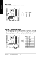
..." is only supported by rear USB ports. Definition 1 Power 2 Power 9 1 3 USB DX- 4 USB Dy- 10 2 5 USB DX+ 6 USB Dy+ 7 GND 8 GND 9 No Pin 10 NC GA-8I915G-MF/GA-8I915GM Motherboard - 24 - Definition 1 CD-L 2 GND 3 GND 4 CD -R 12) F_ USB1 / F_USB2 (Front USB Connector) Be careful with the polarity of the front USB connector. English 11...
..." is only supported by rear USB ports. Definition 1 Power 2 Power 9 1 3 USB DX- 4 USB Dy- 10 2 5 USB DX+ 6 USB Dy+ 7 GND 8 GND 9 No Pin 10 NC GA-8I915G-MF/GA-8I915GM Motherboard - 24 - Definition 1 CD-L 2 GND 3 GND 4 CD -R 12) F_ USB1 / F_USB2 (Front USB Connector) Be careful with the polarity of the front USB connector. English 11...
Manual
Page 26
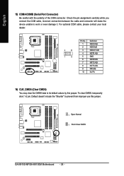
... A/BNRI A/BNo Pin 16) CLR_CMOS (Clear CMOS) You may clear the CMOS data to its default values by this jumper. 1 Open: Normal 1 Short :Clear CMOS GA-8I915G-MF/GA-8I915GM Motherboard - 26 - To clear CMOS, temporarily short 1-2 pin. Check the pin assignment carefully while you connect the COM cable, incorrect connection between the cable and connector...
... A/BNRI A/BNo Pin 16) CLR_CMOS (Clear CMOS) You may clear the CMOS data to its default values by this jumper. 1 Open: Normal 1 Short :Clear CMOS GA-8I915G-MF/GA-8I915GM Motherboard - 26 - To clear CMOS, temporarily short 1-2 pin. Check the pin assignment carefully while you connect the COM cable, incorrect connection between the cable and connector...
Manual
Page 30
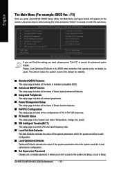
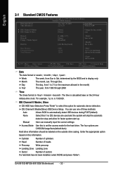
... Defaults Set Supervisor Password Set User Password Save & Exit Setup Exit Without Saving KLJI: Select Item F10: Save & Exit Setup Time, Date, Hard Disk Type... GA-8I915G-MF/GA-8I915GM Motherboard - 30 - This action makes the system reset to search the advanced option hidden. It allows you to limit access to the system and Setup, or...
... Defaults Set Supervisor Password Set User Password Save & Exit Setup Exit Without Saving KLJI: Select Item F10: Save & Exit Setup Time, Date, Hard Disk Type... GA-8I915G-MF/GA-8I915GM Motherboard - 30 - This action makes the system reset to search the advanced option hidden. It allows you to limit access to the system and Setup, or...
Manual
Page 32
... BIOS and is calculated base on this option for automatic device detection. to Dec. For example, 1 p.m. IDE Channel 0 Master(Slave) IDE Device Setup. Through Dec. GA-8I915G-MF/GA-8I915GM Motherboard - 32 - to Sat. Week The week, from 1999 through 2098 Time The times format in the month) Year The year, from Sun to set the...
... BIOS and is calculated base on this option for automatic device detection. to Dec. For example, 1 p.m. IDE Channel 0 Master(Slave) IDE Device Setup. Through Dec. GA-8I915G-MF/GA-8I915GM Motherboard - 32 - to Sat. Week The week, from 1999 through 2098 Time The times format in the month) Year The year, from Sun to set the...
Manual
Page 34
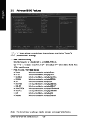
USB-FDD Select your boot device priority by Hard Disk. GA-8I915G-MF/GA-8I915GM Motherboard - 34 - Hard Disk Boot Priority Select boot sequence for onboard(or add-on cards) SCSI, RAID, etc. Use < > or < > to select a device, then press to ...
USB-FDD Select your boot device priority by Hard Disk. GA-8I915G-MF/GA-8I915GM Motherboard - 34 - Hard Disk Boot Priority Select boot sequence for onboard(or add-on cards) SCSI, RAID, etc. Use < > or < > to select a device, then press to ...
Manual
Page 36
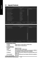
... SATA Port 1/3 Set to Only for PATA IDE. Set On-Chip SATA mode to Enhanced, the motherboard allows up to use up to 6 HDDs to 4 HDDs on the motherboard; 2 for SATA and the other for GA-8I915G-MF. PATA mode. GA-8I915G-MF/GA-8I915GM Motherboard - 36 - BIOS will be simulated to USB Controller USB 2.0 Controller USB Keyboard Support USB Mouse...
... SATA Port 1/3 Set to Only for PATA IDE. Set On-Chip SATA mode to Enhanced, the motherboard allows up to use up to 6 HDDs to 4 HDDs on the motherboard; 2 for SATA and the other for GA-8I915G-MF. PATA mode. GA-8I915G-MF/GA-8I915GM Motherboard - 36 - BIOS will be simulated to USB Controller USB 2.0 Controller USB Keyboard Support USB Mouse...
Manual
Page 38
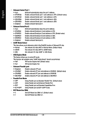
..." doesn't set at Normal. ECP Mode Use DMA 3 Set ECP Mode Use DMA to 3. (Default value) 1 Set ECP Mode Use DMA to seclect IR mode. GA-8I915G-MF/GA-8I915GM Motherboard - 38 - Disable onboard Serial port 2. UR2 Duplex Mode This feature allows you to IrDA Mode. Half IR Function Duplex Half. (Default value) Full IR Function...
..." doesn't set at Normal. ECP Mode Use DMA 3 Set ECP Mode Use DMA to 3. (Default value) 1 Set ECP Mode Use DMA to seclect IR mode. GA-8I915G-MF/GA-8I915GM Motherboard - 38 - Disable onboard Serial port 2. UR2 Duplex Mode This feature allows you to IrDA Mode. Half IR Function Duplex Half. (Default value) Full IR Function...
Manual
Page 40
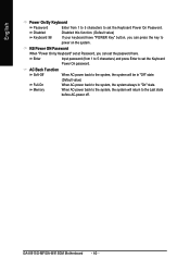
AC Back Function Soft-Off When AC-power back to the system, the system will return to the Last state before AC-power off. GA-8I915G-MF/GA-8I915GM Motherboard - 40 - Memory When AC-power back to the system, the system will be in "On" state. Full-On (Default value) When AC-power back to ...
AC Back Function Soft-Off When AC-power back to the system, the system will return to the Last state before AC-power off. GA-8I915G-MF/GA-8I915GM Motherboard - 40 - Memory When AC-power back to the system, the system will be in "On" state. Full-On (Default value) When AC-power back to ...

Manual
Page 42
... Control Disabled Enabled Disable this function. (Default value) CPU/SYSEM FAN Fail Warning Disabled Enabled Fan warning function disable. (Default value) Fan warning function enable. GA-8I915G-MF/GA-8I915GM Motherboard - 42 - Current CPU Temperature Detect CPU temperature automatically. When the CPU temperature is lower than 65 degrees Celsius, CPU fan will change depending on the...
... Control Disabled Enabled Disable this function. (Default value) CPU/SYSEM FAN Fail Warning Disabled Enabled Fan warning function disable. (Default value) Fan warning function enable. GA-8I915G-MF/GA-8I915GM Motherboard - 42 - Current CPU Temperature Detect CPU temperature automatically. When the CPU temperature is lower than 65 degrees Celsius, CPU fan will change depending on the...

Manual
Page 44
... BIOS Features Load Optimized Defaults ` Integrated Peripherals Set Supervisor Password ` Power Management Setup Set User Password ` PnP/PCI Configurations Load Fail-Safe DefaultsS(aYv/eN&)? GA-8I915G-MF/GA-8I915GM Motherboard - 44 -
... BIOS Features Load Optimized Defaults ` Integrated Peripherals Set Supervisor Password ` Power Management Setup Set User Password ` PnP/PCI Configurations Load Fail-Safe DefaultsS(aYv/eN&)? GA-8I915G-MF/GA-8I915GM Motherboard - 44 -

Manual
Page 46
GA-8I915G-MF/GA-8I915GM Motherboard - 46 - Type "N" will return to Setup Utility. 2-12 Exit Without Saving CMOS Setup Utility-Copyright (C) 1984-2004 Award Software ` Standard CMOS Features ` Advanced BIOS Features ` ...
GA-8I915G-MF/GA-8I915GM Motherboard - 46 - Type "N" will return to Setup Utility. 2-12 Exit Without Saving CMOS Setup Utility-Copyright (C) 1984-2004 Award Software ` Standard CMOS Features ` Advanced BIOS Features ` ...
Manual
Page 48
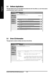
GA-8I915G-MF/GA-8I915GM Motherboard - 48 - English 3-2 Software Applications This page displays all the tools that Gigabyte developed and some free software, you can choose anyone you want and press "install" to install them. 3-3 Driver CD Information This page lists the contents of software and drivers in this CD-title.
GA-8I915G-MF/GA-8I915GM Motherboard - 48 - English 3-2 Software Applications This page displays all the tools that Gigabyte developed and some free software, you can choose anyone you want and press "install" to install them. 3-3 Driver CD Information This page lists the contents of software and drivers in this CD-title.


