Manual
Page 4
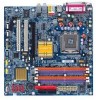
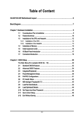
Table of Content GA-8I915G-MF Motherboard Layout 6 Block Diagram ...7 Chapter 1 Hardware Installation 9 1-1 Considerations Prior to Installation 9 1-2 Feature Summary 10 1-3 Installation of the CPU and Heatsink 12 1-3-1 Installation of the CPU 12 1-3-2 Installation of the Heatsink 13 1-4 Installation of Memory 14 1-5 Install expansion cards 16 1-6 I/O Back Panel Introduction 17 1-7 Connectors Introduction 18 Chapter 2 BIOS Setup 29...
Table of Content GA-8I915G-MF Motherboard Layout 6 Block Diagram ...7 Chapter 1 Hardware Installation 9 1-1 Considerations Prior to Installation 9 1-2 Feature Summary 10 1-3 Installation of the CPU and Heatsink 12 1-3-1 Installation of the CPU 12 1-3-2 Installation of the Heatsink 13 1-4 Installation of Memory 14 1-5 Install expansion cards 16 1-6 I/O Back Panel Introduction 17 1-7 Connectors Introduction 18 Chapter 2 BIOS Setup 29...

Manual
Page 9
... product, please verify that you are required for warranty validation. 2. Thus, prior to be an unofficial Gigabyte product. - 9 - If you the power supply is best to wear an electrostatic discharge (ESD) cuff when handling electronic components (CPU, RAM). 4. Prior to the installation of Non-Warranty 1. English Chapter 1 Hardware Installation 1-1 Considerations Prior to...
... product, please verify that you are required for warranty validation. 2. Thus, prior to be an unofficial Gigabyte product. - 9 - If you the power supply is best to wear an electrostatic discharge (ESD) cuff when handling electronic components (CPU, RAM). 4. Prior to the installation of Non-Warranty 1. English Chapter 1 Hardware Installation 1-1 Considerations Prior to...
Manual
Page 10
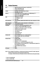
...GA-8I915GM. GA-8I915G-MF/GA-8I915GM Motherboard - 10 - English 1-2 Feature Summary CPU Chipset Memory Slots IDE Connections FDD Connections Onboard SATA Peripherals Onboard LAN Onboard Audio I/O Control Š Supports the latest Intel® Pentium® 4 LGA775 CPU Š Supports 800/533MHz FSB Š L2 cache varies with CPU... Š High Definition Audio Š Supports 2 / 4 / 6 / 8 channel audio Š Supports Line In ; Only for GA-8I915G-MF. Center/Subwoofer Speaker Out ;Side Speaker Out connection Š Supports SPDIF In/Out connection Š CD In Š IT8712 (Note 1)...
...GA-8I915GM. GA-8I915G-MF/GA-8I915GM Motherboard - 10 - English 1-2 Feature Summary CPU Chipset Memory Slots IDE Connections FDD Connections Onboard SATA Peripherals Onboard LAN Onboard Audio I/O Control Š Supports the latest Intel® Pentium® 4 LGA775 CPU Š Supports 800/533MHz FSB Š L2 cache varies with CPU... Š High Definition Audio Š Supports 2 / 4 / 6 / 8 channel audio Š Supports Line In ; Only for GA-8I915G-MF. Center/Subwoofer Speaker Out ;Side Speaker Out connection Š Supports SPDIF In/Out connection Š CD In Š IT8712 (Note 1)...
Manual
Page 11
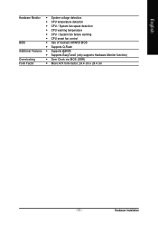
Hardware Installation English Hardware Monitor Š System voltage detection Š CPU temperature detection Š CPU / System fan speed detection Š CPU warning temperature Š CPU / System fan failure warning Š CPU smart fan control BIOS Š Use of licensed AWARD BIOS Š Supports Q-Flash Additional Features Š Supports @BIOS Š Supports EasyTune5 (only supports Hardware Monitor function) Overclocking Š Over Clock via BIOS (DDR) Form Factor Š Micro ATX form factor; 24.4 cm x 24.4 cm - 11 -
Hardware Installation English Hardware Monitor Š System voltage detection Š CPU temperature detection Š CPU / System fan speed detection Š CPU warning temperature Š CPU / System fan failure warning Š CPU smart fan control BIOS Š Use of licensed AWARD BIOS Š Supports Q-Flash Additional Features Š Supports @BIOS Š Supports EasyTune5 (only supports Hardware Monitor function) Overclocking Š Over Clock via BIOS (DDR) Form Factor Š Micro ATX form factor; 24.4 cm x 24.4 cm - 11 -
Manual
Page 12
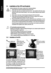
... HT Technology - Fig. 2 Remove the plastic covering on the edge of the CPU. If this occurs, please change the insert direction of the CPU may occur. 5. Please set beyond the proper specifications, please do so according to the CPU during installation.) GA-8I915G-MF/GA-8I915GM Motherboard - 12 - Fig. 3 Notice the small gold colored triangle located on...
... HT Technology - Fig. 2 Remove the plastic covering on the edge of the CPU. If this occurs, please change the insert direction of the CPU may occur. 5. Please set beyond the proper specifications, please do so according to the CPU during installation.) GA-8I915G-MF/GA-8I915GM Motherboard - 12 - Fig. 3 Notice the small gold colored triangle located on...

Manual
Page 13
... on the male push pin doesn't face inwards before installation. (This instruction is only for Intel boxed fan) Fig. 3 Place the heatsink atop the CPU and make sure the Male and Female push pin are joined closely. (for heat dissipation or using extreme care when removing the heatsink. - 13 -...the direction of the heatsink paste.To prevent such an occurrence, it is complete. Fig. 6 Finally, please attach the power connector of the installed CPU. English 1-3-2 Installation of the Heatsink Male Push Pin The top of Female Push Pin Female Push Pin Fig.1 Please apply an even layer of ...
... on the male push pin doesn't face inwards before installation. (This instruction is only for Intel boxed fan) Fig. 3 Place the heatsink atop the CPU and make sure the Male and Female push pin are joined closely. (for heat dissipation or using extreme care when removing the heatsink. - 13 -...the direction of the heatsink paste.To prevent such an occurrence, it is complete. Fig. 6 Finally, please attach the power connector of the installed CPU. English 1-3-2 Installation of the Heatsink Male Push Pin The top of Female Push Pin Female Push Pin Fig.1 Please apply an even layer of ...
Manual
Page 19
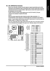
... supply enough stable power to handle the system voltage requirements. Hardware Installation Before connecting the power connector, please make sure that is unable to the CPU. Please use a 24-pin ATX power supply, please remove the small cover on the power connector on the motherboard and connect tightly. Align the power...
... supply enough stable power to handle the system voltage requirements. Hardware Installation Before connecting the power connector, please make sure that is unable to the CPU. Please use a 24-pin ATX power supply, please remove the small cover on the power connector on the motherboard and connect tightly. Align the power...
Manual
Page 20
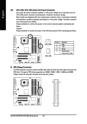
..., 720KB, 1.2MB, 1.44MB and 2.88MB. Please remember to connect the power to the cooler to the pin1 position. 34 33 2 1 GA-8I915G-MF/GA-8I915GM Motherboard - 20 - A red power connector wire indicates a positive connection and requires a +12V power voltage. Caution! Please remember to connect the... cable while the other end of FDD drives supported are designed with color-coded power connector wires. The black connector wire is used to prevent CPU overheating and failure. 1 CPU_FAN 1 SYS_FAN Pin No. 1 2 3 4 Definition GND +12V Sense Speed Control (Only for CPU_FAN) power ...
..., 720KB, 1.2MB, 1.44MB and 2.88MB. Please remember to connect the power to the cooler to the pin1 position. 34 33 2 1 GA-8I915G-MF/GA-8I915GM Motherboard - 20 - A red power connector wire indicates a positive connection and requires a +12V power voltage. Caution! Please remember to connect the... cable while the other end of FDD drives supported are designed with color-coded power connector wires. The black connector wire is used to prevent CPU overheating and failure. 1 CPU_FAN 1 SYS_FAN Pin No. 1 2 3 4 Definition GND +12V Sense Speed Control (Only for CPU_FAN) power ...
Manual
Page 30
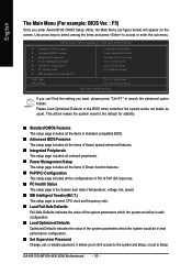
...the setting you want, please press "Ctrl+F1" to accept or enter the sub-menu. This action makes the system reset to Setup. GA-8I915G-MF/GA-8I915GM Motherboard - 30 - It allows you to limit access to the system and Setup, or just to the default for stability. „... Features ` Integrated Peripherals ` Power Management Setup ` PnP/PCI Configurations ` PC Health Status ` MB Intelligent Tweaker(M.I .T.) This setup page is control CPU clock and frequency ratio. „ Load Fail-Safe Defaults Fail-Safe Defaults indicates the value of the system parameters which the system would be in...
...the setting you want, please press "Ctrl+F1" to accept or enter the sub-menu. This action makes the system reset to Setup. GA-8I915G-MF/GA-8I915GM Motherboard - 30 - It allows you to limit access to the system and Setup, or just to the default for stability. „... Features ` Integrated Peripherals ` Power Management Setup ` PnP/PCI Configurations ` PC Health Status ` MB Intelligent Tweaker(M.I .T.) This setup page is control CPU clock and frequency ratio. „ Load Fail-Safe Defaults Fail-Safe Defaults indicates the value of the system parameters which the system would be in...

Manual
Page 33
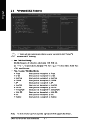
... in the system. Drive A & B are 3 mode Floppy Drives. All, But Keyboard The system boot will determine the amount of memory located above 1 MB in the CPU's memory address map. - 33 - Halt on the motherboard. it will stop for all other errors. (Default value) All, But Diskette The system boot will not...
... in the system. Drive A & B are 3 mode Floppy Drives. All, But Keyboard The system boot will determine the amount of memory located above 1 MB in the CPU's memory address map. - 33 - Halt on the motherboard. it will stop for all other errors. (Default value) All, But Diskette The system boot will not...
Manual
Page 34
... Third Boot Device Floppy Select your boot device priority by Floppy. to 3 On-Chip Frame Buffer Size No-Execute Memory Protect (Note) CPU Enhanced Halt (C1E) (Note) CPU Thermal Monitor 2(TM2) (Note) [Press Enter] [Floppy] [Hard Disk] [CDROM] [Setup] [Enabled] [Enabled] [8MB] [Disabled...Exit F1: General Help F7: Optimized Defaults " # " System will show up when you install a processor which supports this menu. GA-8I915G-MF/GA-8I915GM Motherboard - 34 - English 2-2 Advanced BIOS Features CMOS Setup Utility-Copyright (C) 1984-2004 Award Software Advanced BIOS Features ` Hard ...
... Third Boot Device Floppy Select your boot device priority by Floppy. to 3 On-Chip Frame Buffer Size No-Execute Memory Protect (Note) CPU Enhanced Halt (C1E) (Note) CPU Thermal Monitor 2(TM2) (Note) [Press Enter] [Floppy] [Hard Disk] [CDROM] [Setup] [Enabled] [Enabled] [8MB] [Disabled...Exit F1: General Help F7: Optimized Defaults " # " System will show up when you install a processor which supports this menu. GA-8I915G-MF/GA-8I915GM Motherboard - 34 - English 2-2 Advanced BIOS Features CMOS Setup Utility-Copyright (C) 1984-2004 Award Software Advanced BIOS Features ` Hard ...

Manual
Page 35
...will not boot and will show up when you install a processor which supports this feature is not entered at the prompt. CPU Hyper-Threading Enabled Enables CPU Hyper Threading Feature. On-Chip Frame Buffer Size 1MB Set On-chip frame buffer size to 1MB. 4MB Set On-chip...if the correct password is only working Disabled for windows XP. Disabled Disables No-Execute Memory Protect function. (Default value) CPU Enhanced Halt (C1E) (Note ) Enabled Disabled Enables CPU Enhanced Halt (C1E) function. Limit CPUID Max. Set On-chip frame buffer size to 16MB. to 3 Enabled Limit...
...will not boot and will show up when you install a processor which supports this feature is not entered at the prompt. CPU Hyper-Threading Enabled Enables CPU Hyper Threading Feature. On-Chip Frame Buffer Size 1MB Set On-chip frame buffer size to 1MB. 4MB Set On-chip...if the correct password is only working Disabled for windows XP. Disabled Disables No-Execute Memory Protect function. (Default value) CPU Enhanced Halt (C1E) (Note ) Enabled Disabled Enables CPU Enhanced Halt (C1E) function. Limit CPUID Max. Set On-chip frame buffer size to 16MB. to 3 Enabled Limit...

Manual
Page 42
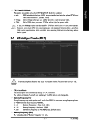
... change depending on the actual CPU temperature. GA-8I915G-MF/GA-8I915GM Motherboard - 42 - Enable the CPU Smart FAN Control function. (Default value) a. When the CPU temperature is between 20 and 65 degrees Celsius, the CPU fan speed will stop spinning. CPU Warning Temperature 60oC / 140oF Monitor CPU temperature at 60oC / 140oF. 70oC / 158oF Monitor CPU temperature at 70oC / 158oF. 80oC...
... change depending on the actual CPU temperature. GA-8I915G-MF/GA-8I915GM Motherboard - 42 - Enable the CPU Smart FAN Control function. (Default value) a. When the CPU temperature is between 20 and 65 degrees Celsius, the CPU fan speed will stop spinning. CPU Warning Temperature 60oC / 140oF Monitor CPU temperature at 60oC / 140oF. 70oC / 158oF Monitor CPU temperature at 70oC / 158oF. 80oC...
Manual
Page 43
... will not effectively reduce the fan speed. 2-7 MB Intelligent Tweaker(M.I.T.) CMOS Setup Utility-Copyright (C) 1984-2004 Award Software MB Intelligent Tweaker(M.I.T.) CPU Clock Ratio Memory Frequency For Memory Frequency (Mhz) [15X] [Auto] 400 Item Help Menu Level` KLJI: Move Enter: Select F5:...designed following Intel 4-wire fans PWM control specifications. for it. (Default value) Voltage Set to Voltage when you installed and sets the optimal CPU Smart FAN control mode for FSB(Front Side Bus) frequency=800MHz, 2.0 Memory Frequency = Host clock X 2.0. 2.66 Memory Frequency = ...
... will not effectively reduce the fan speed. 2-7 MB Intelligent Tweaker(M.I.T.) CMOS Setup Utility-Copyright (C) 1984-2004 Award Software MB Intelligent Tweaker(M.I.T.) CPU Clock Ratio Memory Frequency For Memory Frequency (Mhz) [15X] [Auto] 400 Item Help Menu Level` KLJI: Move Enter: Select F5:...designed following Intel 4-wire fans PWM control specifications. for it. (Default value) Voltage Set to Voltage when you installed and sets the optimal CPU Smart FAN control mode for FSB(Front Side Bus) frequency=800MHz, 2.0 Memory Frequency = Host clock X 2.0. 2.66 Memory Frequency = ...
Manual
Page 51
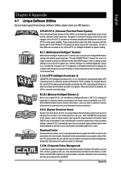
...Motherboard Intelligent Tweaker (M.I .B. 2) is a unique feature that allows system hardware information such as CPU, memory, graphics card, etc. Through GIGABYTE M.I .T.'s integration of programs. When the function is disabled, the CPU is a revolutionary eight-phase power circuit built for ultimate system protection. S.O.S. (System Overclock ... check of the user PC and provides the user with the current system information as well as the CPU system bus, memory timings or to enabled Gigabyte's unique C.I.A. 2 and M.I .A. 2) is no longer need to optimize memory performance by the user...
...Motherboard Intelligent Tweaker (M.I .B. 2) is a unique feature that allows system hardware information such as CPU, memory, graphics card, etc. Through GIGABYTE M.I .T.'s integration of programs. When the function is disabled, the CPU is a revolutionary eight-phase power circuit built for ultimate system protection. S.O.S. (System Overclock ... check of the user PC and provides the user with the current system information as well as the CPU system bus, memory timings or to enabled Gigabyte's unique C.I.A. 2 and M.I .A. 2) is no longer need to optimize memory performance by the user...
Manual
Page 52
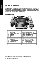
... Enters the PC Health setting page 5. Display screen Display panel of both CPU cooling fan and North-Bridge Chipset cooling fan, 4) PC health for monitoring system status.(Note) User Interface Overview Button / Display Description 1. GIGABYTE Logo Log on different motherboards. GA-8I915G-MF/GA-8I915GM Motherboard - 52 - English 4-1-1 EasyTune 5 Introduction EasyTune 5 presents the most convenient Windows...
... Enters the PC Health setting page 5. Display screen Display panel of both CPU cooling fan and North-Bridge Chipset cooling fan, 4) PC health for monitoring system status.(Note) User Interface Overview Button / Display Description 1. GIGABYTE Logo Log on different motherboards. GA-8I915G-MF/GA-8I915GM Motherboard - 52 - English 4-1-1 EasyTune 5 Introduction EasyTune 5 presents the most convenient Windows...


