Manual
Page 1
GA-8I865G775-G / GA-8I865G775-G-RH Intel® Pentium® 4 LGA775 Processor Motherboard User's Manual Rev. 2002 12ME-8I865GTG-2002R * The WEEE marking on the product indicates this product must not be disposed of with user's other household waste and must be handed over to a designated collection point for the recycling of waste electrical and electronic equipment!! * The WEEE marking applies only in European Union's member states.
GA-8I865G775-G / GA-8I865G775-G-RH Intel® Pentium® 4 LGA775 Processor Motherboard User's Manual Rev. 2002 12ME-8I865GTG-2002R * The WEEE marking on the product indicates this product must not be disposed of with user's other household waste and must be handed over to a designated collection point for the recycling of waste electrical and electronic equipment!! * The WEEE marking applies only in European Union's member states.

Manual
Page 5
Table of Contents ItemChecklist ...7 OptionalAccessories ...7 GA-8I865G775-G(-RH) Motherboard Layout 8 Block Diagram ...9 Chapter 1 Hardware Installation 11 1-1 Considerations Prior to Installation 11 1-2 Feature Summary 12 1-3 Installation of the CPU and Heatsink 14 1-3-1 Installation of ...
Table of Contents ItemChecklist ...7 OptionalAccessories ...7 GA-8I865G775-G(-RH) Motherboard Layout 8 Block Diagram ...9 Chapter 1 Hardware Installation 11 1-1 Considerations Prior to Installation 11 1-2 Feature Summary 12 1-3 Installation of the CPU and Heatsink 14 1-3-1 Installation of ...

Manual
Page 8
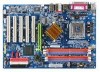
GA-8I865G775-G(-RH) Motherboard Layout KB_MS LGA775 ATX_12V CPU_FAN COMA LPT GA-8I865G775 -G(-RH) DDR1 VGA ATX R_USB USB_LAN AUDIO F_AUDIO Intel 865G DDR4 DDR3 DDR2 AGP Marvell 8001 CODEC CD_IN SUR_CEN IT8712 AUX_IN CI COMB SPDIF_O PCI1 ICH5 PCI2 IDE1 IDE2 BAT CLR_CMOS FDD PCI3 SATA0 PCI4 BIOS SATA1 PCI5 SYS _FAN F_USB1 F_USB2 F_PANEL PWR_LED - 8 -
GA-8I865G775-G(-RH) Motherboard Layout KB_MS LGA775 ATX_12V CPU_FAN COMA LPT GA-8I865G775 -G(-RH) DDR1 VGA ATX R_USB USB_LAN AUDIO F_AUDIO Intel 865G DDR4 DDR3 DDR2 AGP Marvell 8001 CODEC CD_IN SUR_CEN IT8712 AUX_IN CI COMB SPDIF_O PCI1 ICH5 PCI2 IDE1 IDE2 BAT CLR_CMOS FDD PCI3 SATA0 PCI4 BIOS SATA1 PCI5 SYS _FAN F_USB1 F_USB2 F_PANEL PWR_LED - 8 -

Manual
Page 12
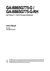
... connector Š 1 AUX In connector Š 1 Surround Center connector Š 1 SPDIF Out connector Š 1 power LED connector Š 2 USB 2.0/1.1 connectors for additional 4 ports by cables GA-8I865G775-G(-RH) Motherboard - 12 -
... connector Š 1 AUX In connector Š 1 Surround Center connector Š 1 SPDIF Out connector Š 1 power LED connector Š 2 USB 2.0/1.1 connectors for additional 4 ports by cables GA-8I865G775-G(-RH) Motherboard - 12 -
Manual
Page 14
.... Chipset: An Intel® Chipset that the system bus frequency be set beyond the proper specifications, please do so according to the CPU during installation.) GA-8I865G775-G(-RH) Motherboard - 14 - If you wish to system use, otherwise overheating and permanent damage of the CPU may occur. 5. Please add an even layer of the...
.... Chipset: An Intel® Chipset that the system bus frequency be set beyond the proper specifications, please do so according to the CPU during installation.) GA-8I865G775-G(-RH) Motherboard - 14 - If you wish to system use, otherwise overheating and permanent damage of the CPU may occur. 5. Please add an even layer of the...

Manual
Page 16
... Before installing the memory modules, please comply with each slot. The memory capacity used can only fit in one direction. DDR memory module Fig. 1 Fig. 2 GA-8I865G775-G(-RH) Motherboard - 16 - Insert the DIMM memory module vertically into the DIMM socket. Reverse the installation steps when you are designed so that the computer power...
... Before installing the memory modules, please comply with each slot. The memory capacity used can only fit in one direction. DDR memory module Fig. 1 Fig. 2 GA-8I865G775-G(-RH) Motherboard - 16 - Insert the DIMM memory module vertically into the DIMM socket. Reverse the installation steps when you are designed so that the computer power...
Manual
Page 18
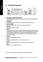
... interface. Also make sure your OS supports USB controller. If your OS or device(s) vendors. You can be connected to Serial port. channel audio functioning. GA-8I865G775-G(-RH) Motherboard - 18 -
... interface. Also make sure your OS supports USB controller. If your OS or device(s) vendors. You can be connected to Serial port. channel audio functioning. GA-8I865G775-G(-RH) Motherboard - 18 -

Manual
Page 20
... +12V Pin No. Align the power connector with its proper location on /off) 15 GND 16 GND 17 GND 18 -5V 19 +5V 20 +5V GA-8I865G775-G(-RH) Motherboard - 20 - English 1/2) ATX_12V/ATX (Power Connector) With the use of the power connector, the power supply can withstand high power consumption be used (300W...
... +12V Pin No. Align the power connector with its proper location on /off) 15 GND 16 GND 17 GND 18 -5V 19 +5V 20 +5V GA-8I865G775-G(-RH) Motherboard - 20 - English 1/2) ATX_12V/ATX (Power Connector) With the use of the power connector, the power supply can withstand high power consumption be used (300W...

Manual
Page 22
... used to connect the FDD cable while the other end of the cable connects to work properly. Definition 1 GND 7 1 2 TXP 3 TXN 4 GND 5 RXN 6 RXP 7 GND GA-8I865G775-G(-RH) Motherboard - 22 - The types of the foolproof groove in order to the FDD drive. Before attaching the FDD cable, please take note of FDD drives...
... used to connect the FDD cable while the other end of the cable connects to work properly. Definition 1 GND 7 1 2 TXP 3 TXN 4 GND 5 RXN 6 RXP 7 GND GA-8I865G775-G(-RH) Motherboard - 22 - The types of the foolproof groove in order to the FDD drive. Before attaching the FDD cable, please take note of FDD drives...

Manual
Page 24
Definition 1 MIC 2 GND 1 2 3 MIC_BIAS 4 POWER 9 10 5 FrontAudio(R) 6 Rear Audio (R)/ Return R 7 NC 8 No Pin 9 FrontAudio (L) 10 Rear Audio (L)/ Return L GA-8I865G775-G(-RH) Motherboard - 24 - To find out if the chassis you are the same as the pin assigments on the MB header. Definition 1 MPD+ 1 2 MPD- 3 MPD- 10) ...
Definition 1 MIC 2 GND 1 2 3 MIC_BIAS 4 POWER 9 10 5 FrontAudio(R) 6 Rear Audio (R)/ Return R 7 NC 8 No Pin 9 FrontAudio (L) 10 Rear Audio (L)/ Return L GA-8I865G775-G(-RH) Motherboard - 24 - To find out if the chassis you are the same as the pin assigments on the MB header. Definition 1 MPD+ 1 2 MPD- 3 MPD- 10) ...

Manual
Page 26
... (SPDIF Out) The SPDIF output is capable of the SPDIFO connector. Pin No. Use this feature only when your local dealer. Definition 1 Power 1 2 SPDIFO 3 GND GA-8I865G775-G(-RH) Motherboard - 26 - Be careful with the polarity of providing digital audio to external speakers or compressed AC3 data to work or even damage it. Incorrect...
... (SPDIF Out) The SPDIF output is capable of the SPDIFO connector. Pin No. Use this feature only when your local dealer. Definition 1 Power 1 2 SPDIFO 3 GND GA-8I865G775-G(-RH) Motherboard - 26 - Be careful with the polarity of providing digital audio to external speakers or compressed AC3 data to work or even damage it. Incorrect...

Manual
Page 28
Pin No. Default doesn't include the jumper to detect if the chassis cover is removed. English 17) CI (Chassis Intrusion, Case Open) This 2-pin connector allows your system to avoid improper use of this header. To clear CMOS, temporarily short the two pins. You can check the "Case Opened" status in BIOS Setup. Open: Normal Short: Clear CMOS GA-8I865G775-G(-RH) Motherboard - 28 - Definition 1 1 Signal 2 GND 18) CLR_CMOS (Clear CMOS) You may clear the CMOS data to its default values by this header.
Pin No. Default doesn't include the jumper to detect if the chassis cover is removed. English 17) CI (Chassis Intrusion, Case Open) This 2-pin connector allows your system to avoid improper use of this header. To clear CMOS, temporarily short the two pins. You can check the "Case Opened" status in BIOS Setup. Open: Normal Short: Clear CMOS GA-8I865G775-G(-RH) Motherboard - 28 - Definition 1 1 Signal 2 GND 18) CLR_CMOS (Clear CMOS) You may clear the CMOS data to its default values by this header.

Manual
Page 32
... to accept . The BIOS Setup menus described in the BIOS when somehow the system works not stable as figure below) will appear on cards) device. GA-8I865G775-G D7 . . . . :BIOS Setup/Q-Flash, : Xpress Recovery2, For Boot Menu 02/22/2006-i865G-6A79AG0VC-00 For Boot Menu Use < > ...or < > to select a device, then press enter to accept or enter the sub-menu. GA-8I865G775-G(-RH) Motherboard - 32 - Please Load Optimized Defaults in this menu. CMOS Setup Utility-Copyright (C) 1984-2006 Award Software ` Standard CMOS Features ` Advanced ...
... to accept . The BIOS Setup menus described in the BIOS when somehow the system works not stable as figure below) will appear on cards) device. GA-8I865G775-G D7 . . . . :BIOS Setup/Q-Flash, : Xpress Recovery2, For Boot Menu 02/22/2006-i865G-6A79AG0VC-00 For Boot Menu Use < > ...or < > to select a device, then press enter to accept or enter the sub-menu. GA-8I865G775-G(-RH) Motherboard - 32 - Please Load Optimized Defaults in this menu. CMOS Setup Utility-Copyright (C) 1984-2006 Award Software ` Standard CMOS Features ` Advanced ...

Manual
Page 34
...: • Auto Allows BIOS to automatically detect IDE devices during POST(default) • None Select this if no IDE devices are : Large/Auto(default:Auto) GA-8I865G775-G(-RH) Motherboard - 34 - IDE Channel 2/3 Master IDE HDD Auto-Detection Press "Enter" to set the access mode for automatic device detection. Extended IDE Drive You can...
...: • Auto Allows BIOS to automatically detect IDE devices during POST(default) • None Select this if no IDE devices are : Large/Auto(default:Auto) GA-8I865G775-G(-RH) Motherboard - 34 - IDE Channel 2/3 Master IDE HDD Auto-Detection Press "Enter" to set the access mode for automatic device detection. Extended IDE Drive You can...

Manual
Page 36
... Select boot sequence for onboard(or add-on cards) SCSI, RAID, etc. First / Second / Third Boot Device Floppy Select your boot device priority by Floppy. GA-8I865G775-G(-RH) Motherboard - 36 - USB-ZIP Select your boot device priority by USB-ZIP. USB-CDROM Select your boot device priority by USB-CDROM. Setup The system...
... Select boot sequence for onboard(or add-on cards) SCSI, RAID, etc. First / Second / Third Boot Device Floppy Select your boot device priority by Floppy. GA-8I865G775-G(-RH) Motherboard - 36 - USB-ZIP Select your boot device priority by USB-ZIP. USB-CDROM Select your boot device priority by USB-CDROM. Setup The system...
Manual
Page 38
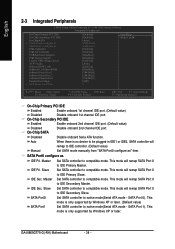
IDE Sec. IDE Sec. This mode is only supported by Windows XP or later. GA-8I865G775-G(-RH) Motherboard - 38 - On-Chip Secondary PCI IDE Enabled Enable onboard 2nd channel IDE port. (Default value) Disabled On-Chip SATA Disable onboard 2nd channel IDE ...
IDE Sec. IDE Sec. This mode is only supported by Windows XP or later. GA-8I865G775-G(-RH) Motherboard - 38 - On-Chip Secondary PCI IDE Enabled Enable onboard 2nd channel IDE port. (Default value) Disabled On-Chip SATA Disable onboard 2nd channel IDE ...

Manual
Page 40
... is 378/IRQ7. (Default value) Enable onboard LPT port and address is 278/IRQ5. 3BC/IRQ7 Enable onboard LPT port and address is 3BC/IRQ7. GA-8I865G775-G(-RH) Motherboard - 40 -
... is 378/IRQ7. (Default value) Enable onboard LPT port and address is 278/IRQ5. 3BC/IRQ7 Enable onboard LPT port and address is 3BC/IRQ7. GA-8I865G775-G(-RH) Motherboard - 40 -

Manual
Page 42
... be in "Off" state. (Default value) Full-On When AC-power back to the system, the system always in Date/Time to set the password. GA-8I865G775-G(-RH) Motherboard - 42 - Enter Input password(from 1 to 5 characters to set the keyboard power on the system. KB Power ON Password When "Power On by Alarm...
... be in "Off" state. (Default value) Full-On When AC-power back to the system, the system always in Date/Time to set the password. GA-8I865G775-G(-RH) Motherboard - 42 - Enter Input password(from 1 to 5 characters to set the keyboard power on the system. KB Power ON Password When "Power On by Alarm...

Manual
Page 44
.... 70oC / 158oF 80oC / 176oF Monitor CPU temperature at 90oC / 194oF. Monitor CPU temperature at 80oC / 176oF. 90oC / 194oF Disabled Monitor CPU temperature at 70oC / 158oF. GA-8I865G775-G(-RH) Motherboard - 44 - Current Voltage(V) Vcore / DDR25V / +3.3V / +12V Detect system's voltage status automatically. If the case have been opened, "Case Opened" will restart. Disable this...
.... 70oC / 158oF 80oC / 176oF Monitor CPU temperature at 90oC / 194oF. Monitor CPU temperature at 80oC / 176oF. 90oC / 194oF Disabled Monitor CPU temperature at 70oC / 158oF. GA-8I865G775-G(-RH) Motherboard - 44 - Current Voltage(V) Vcore / DDR25V / +3.3V / +12V Detect system's voltage status automatically. If the case have been opened, "Case Opened" will restart. Disable this...
Manual
Page 46
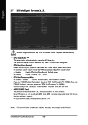
... install a processor which supports this function. Serial ATA device is not changeable. Incorrect using these features may make Serial ATA device function can't work properly. GA-8I865G775-G(-RH) Motherboard - 46 - The option will be available when "CPU Host Clock Control" is overclocked and cannot restart, please wait 20secs. for automatic system restart or...
... install a processor which supports this function. Serial ATA device is not changeable. Incorrect using these features may make Serial ATA device function can't work properly. GA-8I865G775-G(-RH) Motherboard - 46 - The option will be available when "CPU Host Clock Control" is overclocked and cannot restart, please wait 20secs. for automatic system restart or...


