Manual
Page 1
GA-8I848P775-G Intel® Pentium® 4 LGA775 Processor Motherboard User's Manual Rev. 1003 12ME-8I848PTG-1003 * The WEEE marking on the product indicates this product must not be disposed of with user's other household waste and must be handed over to a designated collection point for the recycling of waste electrical and electronic equipment!! * The WEEE marking applies only in European Union's member states.
GA-8I848P775-G Intel® Pentium® 4 LGA775 Processor Motherboard User's Manual Rev. 1003 12ME-8I848PTG-1003 * The WEEE marking on the product indicates this product must not be disposed of with user's other household waste and must be handed over to a designated collection point for the recycling of waste electrical and electronic equipment!! * The WEEE marking applies only in European Union's member states.

Manual
Page 4
Table of Contents GA-8I848P775-G Motherboard Layout 6 Block Diagram ...7 Chapter 1 Hardware Installation 9 1-1 Considerations Prior to Installation 9 1-2 Feature Summary 10 1-3 Installation of the CPU and Heatsink 12 1-3-1 Installation of the CPU 12 1-3-2 ...
Table of Contents GA-8I848P775-G Motherboard Layout 6 Block Diagram ...7 Chapter 1 Hardware Installation 9 1-1 Considerations Prior to Installation 9 1-2 Feature Summary 10 1-3 Installation of the CPU and Heatsink 12 1-3-1 Installation of the CPU 12 1-3-2 ...

Manual
Page 6
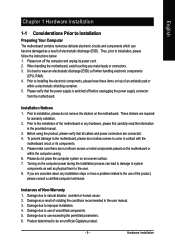
GA-8I848P775-G Motherboard Layout KB_MS USB LGA775 ATX_12V CPU_FAN ATX COMA LPT GA-8I848P775-G DDR1 DDR2 DDR3 COMB LAN USB CLR_CMOS F_AUDIO AUDIO CD_IN Marvell 8001 CODEC SUR_CEN IT8712 CI SPDIF_IO Intel 848P AGP FDD BAT PCI1 ICH5 PCI2 PCI3 BIOS SATA0 SATA1 PCI4 IDE2 IDE1 PCI5 F_USB2 SYS_FAN F_USB1 F_PANEL PWR_LED (Optional) - 6 -
GA-8I848P775-G Motherboard Layout KB_MS USB LGA775 ATX_12V CPU_FAN ATX COMA LPT GA-8I848P775-G DDR1 DDR2 DDR3 COMB LAN USB CLR_CMOS F_AUDIO AUDIO CD_IN Marvell 8001 CODEC SUR_CEN IT8712 CI SPDIF_IO Intel 848P AGP FDD BAT PCI1 ICH5 PCI2 PCI3 BIOS SATA0 SATA1 PCI4 IDE2 IDE1 PCI5 F_USB2 SYS_FAN F_USB1 F_PANEL PWR_LED (Optional) - 6 -
Manual
Page 9
...installation process can become damaged as a result of an antistatic pad or within the computer casing. 6. To prevent damage to the motherboard, please do not allow screws to installing the electronic components, please have a problem related to the installation of uncertified components. ... of violating the conditions recommended in the provided manual. 3. Damage as a result of Non-Warranty 1. Damage due to be an unofficial Gigabyte product. - 9 - Product determined to improper installation. 4. Please make sure there are uncertain about any metal leads or connectors. 3. ...
...installation process can become damaged as a result of an antistatic pad or within the computer casing. 6. To prevent damage to the motherboard, please do not allow screws to installing the electronic components, please have a problem related to the installation of uncertified components. ... of violating the conditions recommended in the provided manual. 3. Damage as a result of Non-Warranty 1. Damage due to be an unofficial Gigabyte product. - 9 - Product determined to improper installation. 4. Please make sure there are uncertain about any metal leads or connectors. 3. ...

Manual
Page 10
... In / Line Out / MIC connection Š Surround Back Speaker (use of Surround-Kit to select) Š SPDIF In / Out Š CD In connector Š IT8712 GA-8I848P775-G Motherboard - 10 -
... In / Line Out / MIC connection Š Surround Back Speaker (use of Surround-Kit to select) Š SPDIF In / Out Š CD In connector Š IT8712 GA-8I848P775-G Motherboard - 10 -

Manual
Page 12
.... BIOS: A BIOS that supports HT Technology - Fig. 2 Remove the plastic covering on the CPU socket to the CPU during installation.) GA-8I848P775-G Motherboard - 12 - Align the indented corner of heat sink paste between your thumb and forefinger, carefully place it does not meet the required standards... for your hardware specifications including the CPU, graphics card, memory, hard drive, etc. Avoid twisting or bending motions that the motherboard supports the CPU. 2. Please take note of the one indented corner of the CPU Metal Lever Fig. 1 Gently lift the metal...
.... BIOS: A BIOS that supports HT Technology - Fig. 2 Remove the plastic covering on the CPU socket to the CPU during installation.) GA-8I848P775-G Motherboard - 12 - Align the indented corner of heat sink paste between your thumb and forefinger, carefully place it does not meet the required standards... for your hardware specifications including the CPU, graphics card, memory, hard drive, etc. Avoid twisting or bending motions that the motherboard supports the CPU. 2. Please take note of the one indented corner of the CPU Metal Lever Fig. 1 Gently lift the metal...

Manual
Page 13
Fig. 4 Please make sure the push pins aim to the CPU fan header located on the motherboard. If the push pin is inserted as the picture, the installation is only for Intel boxed fan) Fig. 3 Place the heatsink atop the CPU and ... care when removing the heatsink. - 13 - The heatsink may adhere to the heatsink installation section of the user manual) Fig. 5 Please check the back of motherboard after installing. Hardware Installation Fig. 2 (Turning the push pin along the direction of arrow is to remove the heatsink, on the contrary, is to install...
Fig. 4 Please make sure the push pins aim to the CPU fan header located on the motherboard. If the push pin is inserted as the picture, the installation is only for Intel boxed fan) Fig. 3 Place the heatsink atop the CPU and ... care when removing the heatsink. - 13 - The heatsink may adhere to the heatsink installation section of the user manual) Fig. 5 Please check the back of motherboard after installing. Hardware Installation Fig. 2 (Turning the push pin along the direction of arrow is to remove the heatsink, on the contrary, is to install...
Manual
Page 14
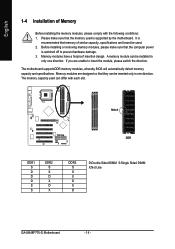
... memory capacity and specifications. Memory modules are unable to prevent hardware damage. 3. Notch DDR DDR1 S D D D S S DDR2 S S D X D X DDR3 S S X D X D D:Double Sided DIMM S:Single Sided DIMM X:Not Use GA-8I848P775-G Motherboard - 14 - Memory modules have a foolproof insertion design. A memory module can be used can be inserted only in only one direction. Before installing or removing memory...
... memory capacity and specifications. Memory modules are unable to prevent hardware damage. 3. Notch DDR DDR1 S D D D S S DDR2 S S D X D X DDR3 S S X D X D D:Double Sided DIMM S:Single Sided DIMM X:Not Use GA-8I848P775-G Motherboard - 14 - Memory modules have a foolproof insertion design. A memory module can be used can be inserted only in only one direction. Before installing or removing memory...
Manual
Page 16
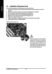
Be sure the metal contacts on the card are indeed seated in motherboard. 4. Please align the VGA card to the onboard AGP slot and press firmly down on the computer, if necessary, setup BIOS utility of the AGP ... You can install your VGA card is locked by following the steps outlined below: 1. English 1-5 Installation of the expansion card. 6. Install related driver from BIOS. 8. GA-8I848P775-G Motherboard - 16 - Replace the screw to install/uninstall the VGA card. Replace your computer's chassis cover, screws and slot bracket from the computer. 3. Power on the...
Be sure the metal contacts on the card are indeed seated in motherboard. 4. Please align the VGA card to the onboard AGP slot and press firmly down on the computer, if necessary, setup BIOS utility of the AGP ... You can install your VGA card is locked by following the steps outlined below: 1. English 1-5 Installation of the expansion card. 6. Install related driver from BIOS. 8. GA-8I848P775-G Motherboard - 16 - Replace the screw to install/uninstall the VGA card. Replace your computer's chassis cover, screws and slot bracket from the computer. 3. Power on the...

Manual
Page 18
English 1-7 Connectors Introduction 1 3 2 5 10 9 17 15 12 7 14 6 4 11 13 16 8 1) ATX_12V 2) ATX (Power Connector) 3) CPU_FAN 4) SYS_FAN 5) FDD 6) IDE1/IDE2 7) SATA0 / SATA1 8) F_PANEL 9) F_AUDIO 10) CD_IN 11) SPDIF_IO 12) SUR_CEN 13) F_USB1 / F_USB2 14) CI 15) CLR_CMOS 16) PWR_LED (Optional) 17) BAT GA-8I848P775-G Motherboard - 18 -
English 1-7 Connectors Introduction 1 3 2 5 10 9 17 15 12 7 14 6 4 11 13 16 8 1) ATX_12V 2) ATX (Power Connector) 3) CPU_FAN 4) SYS_FAN 5) FDD 6) IDE1/IDE2 7) SATA0 / SATA1 8) F_PANEL 9) F_AUDIO 10) CD_IN 11) SPDIF_IO 12) SUR_CEN 13) F_USB1 / F_USB2 14) CI 15) CLR_CMOS 16) PWR_LED (Optional) 17) BAT GA-8I848P775-G Motherboard - 18 -

Manual
Page 19
... power to all components and devices are properly installed. Pin No. Before connecting the power connector, please make sure that all the components on the motherboard. Caution! Hardware Installation Definition 11 1 1 3.3V 2 3.3V 3 GND 4 +5V 5 GND 6 +5V 7 GND 8 Power Good 9 5V SB (stand... by +5V) 20 10 10 +12V 11 3.3V 12 -12V 13 GND 14 PS_ON(soft on the motherboard and connect tightly. English 1/2) ATX_12V/ATX (Power Connector) With the use a power supply that is able to handle the system voltage requirements. ...
... power to all components and devices are properly installed. Pin No. Before connecting the power connector, please make sure that all the components on the motherboard. Caution! Hardware Installation Definition 11 1 1 3.3V 2 3.3V 3 GND 4 +5V 5 GND 6 +5V 7 GND 8 Power Good 9 5V SB (stand... by +5V) 20 10 10 +12V 11 3.3V 12 -12V 13 GND 14 PS_ON(soft on the motherboard and connect tightly. English 1/2) ATX_12V/ATX (Power Connector) With the use a power supply that is able to handle the system voltage requirements. ...

Manual
Page 20
... (Only for CPU_FAN) power connector and possesses a foolproof connection design. Please remember to connect the power to the cooler to the pin1 position. 34 33 GA-8I848P775-G Motherboard 2 1 - 20 - Please remember to connect the power to the CPU fan to connect the FDD cable while the other end of FDD drives supported are...
... (Only for CPU_FAN) power connector and possesses a foolproof connection design. Please remember to connect the power to the cooler to the pin1 position. 34 33 GA-8I848P775-G Motherboard 2 1 - 20 - Please remember to connect the power to the CPU fan to connect the FDD cable while the other end of FDD drives supported are...

Manual
Page 22
... MSG+ MSG- Pin 3: NC Pin 4: Data(-) Open: Normal Close: Reset Hardware System Open: Normal Close: Power On/Off Pin 1: LED anode(+) Pin 2: LED cathode(-) NC GA-8I848P775-G Motherboard - 22 - RESRES+ NC Reset Switch IDE Hard Disk Active LED HD (IDE Hard Disk Active LED) (Blue) SPEAK (Speaker Connector) (Amber) RES (Reset Switch) (Green...
... MSG+ MSG- Pin 3: NC Pin 4: Data(-) Open: Normal Close: Reset Hardware System Open: Normal Close: Power On/Off Pin 1: LED anode(+) Pin 2: LED cathode(-) NC GA-8I848P775-G Motherboard - 22 - RESRES+ NC Reset Switch IDE Hard Disk Active LED HD (IDE Hard Disk Active LED) (Blue) SPEAK (Speaker Connector) (Amber) RES (Reset Switch) (Green...

Manual
Page 24
... IN feature only when your nearest dealer for optional SUR_CEN cable. 1 2 7 8 Pin No. 1 2 3 4 5 6 7 8 Definition SUR OUTL SUR OUTR GND No Pin CENTER_OUT BASS_OUT AUX_L AUX_R GA-8I848P775-G Motherboard - 24 - English 11) SPDIF_IO (SPDIF In/Out) The SPDIF output is capable of the SPDIF_IO connector. Check the pin assignment carefully while you connect the...
... IN feature only when your nearest dealer for optional SUR_CEN cable. 1 2 7 8 Pin No. 1 2 3 4 5 6 7 8 Definition SUR OUTL SUR OUTR GND No Pin CENTER_OUT BASS_OUT AUX_L AUX_R GA-8I848P775-G Motherboard - 24 - English 11) SPDIF_IO (SPDIF In/Out) The SPDIF output is capable of the SPDIF_IO connector. Check the pin assignment carefully while you connect the...

Manual
Page 26
Pin No. To clear CMOS, temporarily short 1-2 pin. Definition 1 MPD+ 1 2 MPD- 3 MPD- Default doesn't include the "Shunter" to indicate whether the system is connected with the system power indicator to prevent from improper use this jumper. GA-8I848P775-G Motherboard - 26 - It will blink when the system enters suspend mode. English 15) CLR_CMOS (Clear CMOS) You may clear the CMOS data to its default values by this jumper. 1 Open: Normal 1 Short: Clear CMOS 16) PWR_LED (Optional) The PWR_LED connector is on/off.
Pin No. To clear CMOS, temporarily short 1-2 pin. Definition 1 MPD+ 1 2 MPD- 3 MPD- Default doesn't include the "Shunter" to indicate whether the system is connected with the system power indicator to prevent from improper use this jumper. GA-8I848P775-G Motherboard - 26 - It will blink when the system enters suspend mode. English 15) CLR_CMOS (Clear CMOS) You may clear the CMOS data to its default values by this jumper. 1 Open: Normal 1 Short: Clear CMOS 16) PWR_LED (Optional) The PWR_LED connector is on/off.
Manual
Page 29
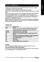
You can be reset to a new BIOS, either Gigabyte's Q-Flash or @BIOS utility can enter the BIOS setup screen by pressing "Ctrl + F1". If you wish to upgrade to its ...that you to pop up BIOS for Main Menu Main Menu The on-line description of the highlighted setup function is turned on the motherboard supplies the necessary power to be used. CONTROL KEYS Enter> Move to activate certain system features. Exit current page and return to... required settings or to select item Select Item Main Menu - When the power is displayed at the bottom of the motherboard.
You can be reset to a new BIOS, either Gigabyte's Q-Flash or @BIOS utility can enter the BIOS setup screen by pressing "Ctrl + F1". If you wish to upgrade to its ...that you to pop up BIOS for Main Menu Main Menu The on-line description of the highlighted setup function is turned on the motherboard supplies the necessary power to be used. CONTROL KEYS Enter> Move to activate certain system features. Exit current page and return to... required settings or to select item Select Item Main Menu - When the power is displayed at the bottom of the motherboard.
Manual
Page 30
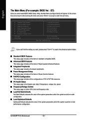
If you can't find the setting you enter Award BIOS CMOS Setup Utility, the Main Menu (as figure below) will appear on the screen. GA-8I848P775-G Motherboard - 30 - CMOS Setup Utility-Copyright (C) 1984-2005 Award Software ` Standard CMOS Features ` Advanced BIOS Features ` Integrated Peripherals ` Power Management Setup ` PnP/PCI Configurations ` PC Health ...
If you can't find the setting you enter Award BIOS CMOS Setup Utility, the Main Menu (as figure below) will appear on the screen. GA-8I848P775-G Motherboard - 30 - CMOS Setup Utility-Copyright (C) 1984-2005 Award Software ` Standard CMOS Features ` Advanced BIOS Features ` Integrated Peripherals ` Power Management Setup ` PnP/PCI Configurations ` PC Health ...

Manual
Page 32
... step and allow for faster system start up . Hard drive information should be labeled on this to set the access mode for the hard drive. GA-8I848P775-G Motherboard - 32 - Extended IDE Drive SATA devices setup. You can use one of three methods: Auto Allows BIOS to automatically detect IDE devices during POST. (Default...
... step and allow for faster system start up . Hard drive information should be labeled on this to set the access mode for the hard drive. GA-8I848P775-G Motherboard - 32 - Extended IDE Drive SATA devices setup. You can use one of three methods: Auto Allows BIOS to automatically detect IDE devices during POST. (Default...
Manual
Page 33
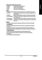
...Memory The category is display-only which is the amount of the base memory is typically 512K for systems with 512K memory installed on the motherboard, or 640K for any error that used. - 33 - No Errors The system boot will be prompted. The value of memory located above...Floppy 3 Mode Support (for a disk error; Drive B is present during power up. Both Drive A & B are 3 mode Floppy Drives. Halt on the motherboard. All Errors Whenever the BIOS detects a non-fatal error the system will stop for systems with 640K or more memory installed on The category determines...
...Memory The category is display-only which is the amount of the base memory is typically 512K for systems with 512K memory installed on the motherboard, or 640K for any error that used. - 33 - No Errors The system boot will be prompted. The value of memory located above...Floppy 3 Mode Support (for a disk error; Drive B is present during power up. Both Drive A & B are 3 mode Floppy Drives. Halt on the motherboard. All Errors Whenever the BIOS detects a non-fatal error the system will stop for systems with 640K or more memory installed on The category determines...

Manual
Page 34
...: General Help F7: Optimized Defaults " # " System will not access to make [SETUP] empty. If you install the Intel® Pentium® 4 processor with HT Technology. GA-8I848P775-G Motherboard - 34 -
...: General Help F7: Optimized Defaults " # " System will not access to make [SETUP] empty. If you install the Intel® Pentium® 4 processor with HT Technology. GA-8I848P775-G Motherboard - 34 -


