Manual
Page 1
GA-8I848P775-G Intel® Pentium® 4 LGA775 Processor Motherboard User's Manual Rev. 1003 12ME-8I848PTG-1003 * The WEEE marking on the product indicates this product must not be disposed of with user's other household waste and must be handed over to a designated collection point for the recycling of waste electrical and electronic equipment!! * The WEEE marking applies only in European Union's member states.
GA-8I848P775-G Intel® Pentium® 4 LGA775 Processor Motherboard User's Manual Rev. 1003 12ME-8I848PTG-1003 * The WEEE marking on the product indicates this product must not be disposed of with user's other household waste and must be handed over to a designated collection point for the recycling of waste electrical and electronic equipment!! * The WEEE marking applies only in European Union's member states.

Manual
Page 4
Table of Contents GA-8I848P775-G Motherboard Layout 6 Block Diagram ...7 Chapter 1 Hardware Installation 9 1-1 Considerations Prior to Installation 9 1-2 Feature Summary 10 1-3 Installation of the CPU and Heatsink 12 1-3-1 Installation of the CPU 12 1-3-2 ...
Table of Contents GA-8I848P775-G Motherboard Layout 6 Block Diagram ...7 Chapter 1 Hardware Installation 9 1-1 Considerations Prior to Installation 9 1-2 Feature Summary 10 1-3 Installation of the CPU and Heatsink 12 1-3-1 Installation of the CPU 12 1-3-2 ...

Manual
Page 6
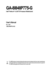
GA-8I848P775-G Motherboard Layout KB_MS USB LGA775 ATX_12V CPU_FAN ATX COMA LPT GA-8I848P775-G DDR1 DDR2 DDR3 COMB LAN USB CLR_CMOS F_AUDIO AUDIO CD_IN Marvell 8001 CODEC SUR_CEN IT8712 CI SPDIF_IO Intel 848P AGP FDD BAT PCI1 ICH5 PCI2 PCI3 BIOS SATA0 SATA1 PCI4 IDE2 IDE1 PCI5 F_USB2 SYS_FAN F_USB1 F_PANEL PWR_LED (Optional) - 6 -
GA-8I848P775-G Motherboard Layout KB_MS USB LGA775 ATX_12V CPU_FAN ATX COMA LPT GA-8I848P775-G DDR1 DDR2 DDR3 COMB LAN USB CLR_CMOS F_AUDIO AUDIO CD_IN Marvell 8001 CODEC SUR_CEN IT8712 CI SPDIF_IO Intel 848P AGP FDD BAT PCI1 ICH5 PCI2 PCI3 BIOS SATA0 SATA1 PCI4 IDE2 IDE1 PCI5 F_USB2 SYS_FAN F_USB1 F_PANEL PWR_LED (Optional) - 6 -
Manual
Page 9
...3. Product determined to improper installation. 4. English Chapter 1 Hardware Installation 1-1 Considerations Prior to Installation Preparing Your Computer The motherboard contains numerous delicate electronic circuits and components which can lead to damage to system components as well as a result of electrostatic... to the installation of the motherboard or any metal leads or connectors. 3. Please do not allow screws to wear an electrostatic discharge (ESD) cuff when handling electronic components (CPU, RAM). 4. Damage due to be an unofficial Gigabyte product. - 9 - Thus, prior ...
...3. Product determined to improper installation. 4. English Chapter 1 Hardware Installation 1-1 Considerations Prior to Installation Preparing Your Computer The motherboard contains numerous delicate electronic circuits and components which can lead to damage to system components as well as a result of electrostatic... to the installation of the motherboard or any metal leads or connectors. 3. Please do not allow screws to wear an electrostatic discharge (ESD) cuff when handling electronic components (CPU, RAM). 4. Damage due to be an unofficial Gigabyte product. - 9 - Thus, prior ...

Manual
Page 10
... In / Line Out / MIC connection Š Surround Back Speaker (use of Surround-Kit to select) Š SPDIF In / Out Š CD In connector Š IT8712 GA-8I848P775-G Motherboard - 10 -
... In / Line Out / MIC connection Š Surround Back Speaker (use of Surround-Kit to select) Š SPDIF In / Out Š CD In connector Š IT8712 GA-8I848P775-G Motherboard - 10 -

Manual
Page 12
...you install the CPU in accordance with HT Technology - Fig. 2 Remove the plastic covering on the CPU prior to the CPU during installation.) GA-8I848P775-G Motherboard - 12 - Chipset: An Intel® Chipset that supports HT Technology and has it into the socket in a straight and downwards motion.... hardware specifications including the CPU, graphics card, memory, hard drive, etc. Fig. 4 Once the CPU is not recommended that the motherboard supports the CPU. 2. English 1-3 Installation of the CPU socket. Please make sure that the system bus frequency be set the CPU ...
...you install the CPU in accordance with HT Technology - Fig. 2 Remove the plastic covering on the CPU prior to the CPU during installation.) GA-8I848P775-G Motherboard - 12 - Chipset: An Intel® Chipset that supports HT Technology and has it into the socket in a straight and downwards motion.... hardware specifications including the CPU, graphics card, memory, hard drive, etc. Fig. 4 Once the CPU is not recommended that the motherboard supports the CPU. 2. English 1-3 Installation of the CPU socket. Please make sure that the system bus frequency be set the CPU ...

Manual
Page 13
...that either thermal tape rather than heat sink paste be used for detailed installation instructions, please refer to the CPU fan header located on the motherboard. Fig. 6 Finally, please attach the power connector of the heatsink to the heatsink installation section of the user manual) Fig. 5 ...Please check the back of motherboard after installing. Hardware Installation The heatsink may adhere to the pin hole on the motherboard.Pressing down the push pins diagonally. If the push pin is inserted as a result of hardening...
...that either thermal tape rather than heat sink paste be used for detailed installation instructions, please refer to the CPU fan header located on the motherboard. Fig. 6 Finally, please attach the power connector of the heatsink to the heatsink installation section of the user manual) Fig. 5 ...Please check the back of motherboard after installing. Hardware Installation The heatsink may adhere to the pin hole on the motherboard.Pressing down the push pins diagonally. If the push pin is inserted as a result of hardening...
Manual
Page 14
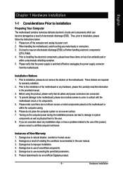
... direction. Please make sure that memory of Memory Before installing the memory modules, please comply with each slot. The motherboard supportsDDR memory modules, whereby BIOS will automatically detect memory capacity and specifications. A memory module can be inserted only in... 1. Notch DDR DDR1 S D D D S S DDR2 S S D X D X DDR3 S S X D X D D:Double Sided DIMM S:Single Sided DIMM X:Not Use GA-8I848P775-G Motherboard - 14 - If you are designed so that the memory used can be installed in one direction. Memory modules have a foolproof insertion design. Memory modules are...
... direction. Please make sure that memory of Memory Before installing the memory modules, please comply with each slot. The motherboard supportsDDR memory modules, whereby BIOS will automatically detect memory capacity and specifications. A memory module can be inserted only in... 1. Notch DDR DDR1 S D D D S S DDR2 S S D X D X DDR3 S S X D X D D:Double Sided DIMM S:Single Sided DIMM X:Not Use GA-8I848P775-G Motherboard - 14 - If you are designed so that the memory used can be installed in one direction. Memory modules have a foolproof insertion design. Memory modules are...
Manual
Page 16
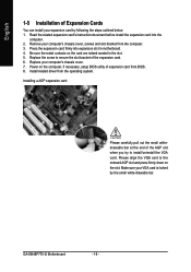
... before install the expansion card into expansion slot in the slot. 5. Be sure the metal contacts on the card are indeed seated in motherboard. 4. Replace your expansion card by the small white-drawable bar. Please align the VGA card to secure the slot bracket of the expansion... bracket from the computer. 3. Power on the slot. Install related driver from BIOS. 8. Press the expansion card firmly into the computer. 2. GA-8I848P775-G Motherboard - 16 - Replace the screw to the onboard AGP slot and press firmly down on the computer, if necessary, setup BIOS utility of the ...
... before install the expansion card into expansion slot in the slot. 5. Be sure the metal contacts on the card are indeed seated in motherboard. 4. Replace your expansion card by the small white-drawable bar. Please align the VGA card to secure the slot bracket of the expansion... bracket from the computer. 3. Power on the slot. Install related driver from BIOS. 8. Press the expansion card firmly into the computer. 2. GA-8I848P775-G Motherboard - 16 - Replace the screw to the onboard AGP slot and press firmly down on the computer, if necessary, setup BIOS utility of the ...

Manual
Page 18
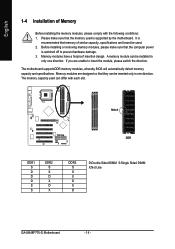
English 1-7 Connectors Introduction 1 3 2 5 10 9 17 15 12 7 14 6 4 11 13 16 8 1) ATX_12V 2) ATX (Power Connector) 3) CPU_FAN 4) SYS_FAN 5) FDD 6) IDE1/IDE2 7) SATA0 / SATA1 8) F_PANEL 9) F_AUDIO 10) CD_IN 11) SPDIF_IO 12) SUR_CEN 13) F_USB1 / F_USB2 14) CI 15) CLR_CMOS 16) PWR_LED (Optional) 17) BAT GA-8I848P775-G Motherboard - 18 -
English 1-7 Connectors Introduction 1 3 2 5 10 9 17 15 12 7 14 6 4 11 13 16 8 1) ATX_12V 2) ATX (Power Connector) 3) CPU_FAN 4) SYS_FAN 5) FDD 6) IDE1/IDE2 7) SATA0 / SATA1 8) F_PANEL 9) F_AUDIO 10) CD_IN 11) SPDIF_IO 12) SUR_CEN 13) F_USB1 / F_USB2 14) CI 15) CLR_CMOS 16) PWR_LED (Optional) 17) BAT GA-8I848P775-G Motherboard - 18 -

Manual
Page 19
Align the power connector with its proper location on the motherboard. Please use of the power connector, the power supply can withstand high power consumption be used that does not provide the required power, the result ...can lead to an unstable system or a system that is recommended that a power supply that all the components on the motherboard and connect tightly. English 1/2) ATX_12V/ATX (Power Connector) With the use a power supply that is able to handle the system voltage requirements. The ATX_12V power...
Align the power connector with its proper location on the motherboard. Please use of the power connector, the power supply can withstand high power consumption be used that does not provide the required power, the result ...can lead to an unstable system or a system that is recommended that a power supply that all the components on the motherboard and connect tightly. English 1/2) ATX_12V/ATX (Power Connector) With the use a power supply that is able to handle the system voltage requirements. The ATX_12V power...

Manual
Page 20
... (Floppy Connector) The FDD connector is the ground wire (GND). Please remember to connect the power to the cooler to the pin1 position. 34 33 GA-8I848P775-G Motherboard 2 1 - 20 - Please remember to connect the power to the CPU fan to the FDD drive. Please connect the red power connector wire to prevent system...
... (Floppy Connector) The FDD connector is the ground wire (GND). Please remember to connect the power to the cooler to the pin1 position. 34 33 GA-8I848P775-G Motherboard 2 1 - 20 - Please remember to connect the power to the CPU fan to the FDD drive. Please connect the red power connector wire to prevent system...

Manual
Page 22
... HD+ HD- Pin 3: NC Pin 4: Data(-) Open: Normal Close: Reset Hardware System Open: Normal Close: Power On/Off Pin 1: LED anode(+) Pin 2: LED cathode(-) NC GA-8I848P775-G Motherboard - 22 - Message LED/ Power/ Sleep LED Speaker Connector Power Switch MSG+ MSG- English 8) F_PANEL (Front Panel Jumper) Please connect the power LED, PC speaker, reset...
... HD+ HD- Pin 3: NC Pin 4: Data(-) Open: Normal Close: Reset Hardware System Open: Normal Close: Power On/Off Pin 1: LED anode(+) Pin 2: LED cathode(-) NC GA-8I848P775-G Motherboard - 22 - Message LED/ Power/ Sleep LED Speaker Connector Power Switch MSG+ MSG- English 8) F_PANEL (Front Panel Jumper) Please connect the power LED, PC speaker, reset...

Manual
Page 24
... this feature only when your nearest dealer for optional SUR_CEN cable. 1 2 7 8 Pin No. 1 2 3 4 5 6 7 8 Definition SUR OUTL SUR OUTR GND No Pin CENTER_OUT BASS_OUT AUX_L AUX_R GA-8I848P775-G Motherboard - 24 - Use SPDIF IN feature only when your device has digital output function.
... this feature only when your nearest dealer for optional SUR_CEN cable. 1 2 7 8 Pin No. 1 2 3 4 5 6 7 8 Definition SUR OUTL SUR OUTR GND No Pin CENTER_OUT BASS_OUT AUX_L AUX_R GA-8I848P775-G Motherboard - 24 - Use SPDIF IN feature only when your device has digital output function.

Manual
Page 26
Default doesn't include the "Shunter" to indicate whether the system is connected with the system power indicator to prevent from improper use this jumper. It will blink when the system enters suspend mode. Pin No. English 15) CLR_CMOS (Clear CMOS) You may clear the CMOS data to its default values by this jumper. 1 Open: Normal 1 Short: Clear CMOS 16) PWR_LED (Optional) The PWR_LED connector is on/off. GA-8I848P775-G Motherboard - 26 - To clear CMOS, temporarily short 1-2 pin. Definition 1 MPD+ 1 2 MPD- 3 MPD-
Default doesn't include the "Shunter" to indicate whether the system is connected with the system power indicator to prevent from improper use this jumper. It will blink when the system enters suspend mode. Pin No. English 15) CLR_CMOS (Clear CMOS) You may clear the CMOS data to its default values by this jumper. 1 Open: Normal 1 Short: Clear CMOS 16) PWR_LED (Optional) The PWR_LED connector is on/off. GA-8I848P775-G Motherboard - 26 - To clear CMOS, temporarily short 1-2 pin. Definition 1 MPD+ 1 2 MPD- 3 MPD-
Manual
Page 29
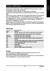
... quickly and easily update or backup BIOS without entering the operating system. @BIOS is turned on the motherboard supplies the necessary power to be used. If you wish to upgrade to a new BIOS, either Gigabyte's Q-Flash or @BIOS utility can enter the BIOS setup screen by pressing "Ctrl + F1". CONTROL KEYS Enter... take you save changes into CMOS Status Page Setup Menu and Option Page Setup Menu - When the power is displayed at the bottom of the motherboard. The CMOS SETUP saves the configuration in the event that you to a disk in the CMOS SRAM of the screen.
... quickly and easily update or backup BIOS without entering the operating system. @BIOS is turned on the motherboard supplies the necessary power to be used. If you wish to upgrade to a new BIOS, either Gigabyte's Q-Flash or @BIOS utility can enter the BIOS setup screen by pressing "Ctrl + F1". CONTROL KEYS Enter... take you save changes into CMOS Status Page Setup Menu and Option Page Setup Menu - When the power is displayed at the bottom of the motherboard. The CMOS SETUP saves the configuration in the event that you to a disk in the CMOS SRAM of the screen.
Manual
Page 30
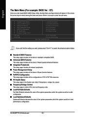
GA-8I848P775-G Motherboard - 30 - English The Main Menu (For example: BIOS Ver. : E7) Once you want, please press "Ctrl+F1" to accept or enter the sub-menu. CMOS ...
GA-8I848P775-G Motherboard - 30 - English The Main Menu (For example: BIOS Ver. : E7) Once you want, please press "Ctrl+F1" to accept or enter the sub-menu. CMOS ...

Manual
Page 32
... system start up . Access Mode Use this to set the access mode for the hard drive. Hard drive information should be labeled on this information. GA-8I848P775-G Motherboard - 32 - Manual User can use one of three methods: Auto Allows BIOS to automatically detect IDE devices during POST. (Default value) None Select this option...
... system start up . Access Mode Use this to set the access mode for the hard drive. Hard drive information should be labeled on this information. GA-8I848P775-G Motherboard - 32 - Manual User can use one of three methods: Auto Allows BIOS to automatically detect IDE devices during POST. (Default value) None Select this option...
Manual
Page 33
Halt on the motherboard. All, But Keyboard The system boot will not stop for all other errors. it will stop for all other All, But Diskette All, But Disk/...-only which is determined by POST (Power On Self Test) of the base memory is typically 512K for systems with 512K memory installed on the motherboard, or 640K for any error that used. - 33 - All Errors Whenever the BIOS detects a non-fatal error the system will be stopped. Both Drive A & B are...
Halt on the motherboard. All, But Keyboard The system boot will not stop for all other errors. it will stop for all other All, But Diskette All, But Disk/...-only which is determined by POST (Power On Self Test) of the base memory is typically 512K for systems with 512K memory installed on the motherboard, or 640K for any error that used. - 33 - All Errors Whenever the BIOS detects a non-fatal error the system will be stopped. Both Drive A & B are...

Manual
Page 34
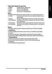
... priority by Hard Disk. ZIP Select your boot device priority by ZIP. Press to make [SETUP] empty. CDROM Select your boot device priority by CDROM. GA-8I848P775-G Motherboard - 34 - Password Check Setup The system will boot but will not access to Setup page if the correct password is not entered at the prompt...
... priority by Hard Disk. ZIP Select your boot device priority by ZIP. Press to make [SETUP] empty. CDROM Select your boot device priority by CDROM. GA-8I848P775-G Motherboard - 34 - Password Check Setup The system will boot but will not access to Setup page if the correct password is not entered at the prompt...


