Manual
Page 4
... Contents...6 Optional Items...6 GA-890FXA-UD7 Motherboard Layout 7 GA-890FXA-UD7 Motherboard Block Diagram 8 Chapter 1 Hardware Installation 9 1-1 Installation Precautions 9 1-2 Product Specifications 10 1-3 Installing the CPU and CPU Cooler 13 1-3-1 Installing the CPU 13 1-3-2 Installing the CPU Cooler 15 1-4 Installing the Hybrid Silent-Pipe Module 16 1-5 Installing the Memory 17 1-5-1 Dual Channel Memory Configuration 17 1-5-2 Installing a Memory 18 1-6 Installing an...
... Contents...6 Optional Items...6 GA-890FXA-UD7 Motherboard Layout 7 GA-890FXA-UD7 Motherboard Block Diagram 8 Chapter 1 Hardware Installation 9 1-1 Installation Precautions 9 1-2 Product Specifications 10 1-3 Installing the CPU and CPU Cooler 13 1-3-1 Installing the CPU 13 1-3-2 Installing the CPU Cooler 15 1-4 Installing the Hybrid Silent-Pipe Module 16 1-5 Installing the Memory 17 1-5-1 Dual Channel Memory Configuration 17 1-5-2 Installing a Memory 18 1-6 Installing an...
Manual
Page 8
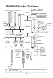
... (33 MHz) (Note 1) To reach DDR3 1866 MHz or above, you must install two memory modules and install them in the DDR3_3 and DDR3_4 memory sockets. (Note 2) Two share the same ports with eSATA. - 8 - GA-890FXA-UD7 Motherboard Block Diagram 4 PCI Express x8 2 PCI Express x16 1 PCI Express x4 or PCIe ... CLK+/- (200 MHz) AM3 CPU DDR3 1866 (O.C.)/1333/1066 MHz (Note 1) Dual Channel Memory Hyper Transport 3.0 1 PCI Express x4 AMD 890FX 1 PCI Express x1 or 2 SATA 3Gb/s ATA-133/100/66/ 33 IDE Channel GIGABYTE x4 x1 SATA2 Switch PCIe CLK (100 MHz) 14 USB 2.0/1.1 (Note 2) PCI Express ...
... (33 MHz) (Note 1) To reach DDR3 1866 MHz or above, you must install two memory modules and install them in the DDR3_3 and DDR3_4 memory sockets. (Note 2) Two share the same ports with eSATA. - 8 - GA-890FXA-UD7 Motherboard Block Diagram 4 PCI Express x8 2 PCI Express x16 1 PCI Express x4 or PCIe ... CLK+/- (200 MHz) AM3 CPU DDR3 1866 (O.C.)/1333/1066 MHz (Note 1) Dual Channel Memory Hyper Transport 3.0 1 PCI Express x4 AMD 890FX 1 PCI Express x1 or 2 SATA 3Gb/s ATA-133/100/66/ 33 IDE Channel GIGABYTE x4 x1 SATA2 Switch PCIe CLK (100 MHz) 14 USB 2.0/1.1 (Note 2) PCI Express ...

Manual
Page 9
... components. • When connecting hardware components to the internal connectors on the computer power during the installation process can become damaged as a motherboard, CPU or memory. Chapter 1 Hardware Installation 1-1 Installation Precautions The motherboard contains numerous delicate electronic circuits and components which can lead to damage to system components as well as...
... components. • When connecting hardware components to the internal connectors on the computer power during the installation process can become damaged as a motherboard, CPU or memory. Chapter 1 Hardware Installation 1-1 Installation Precautions The motherboard contains numerous delicate electronic circuits and components which can lead to damage to system components as well as...
Manual
Page 10
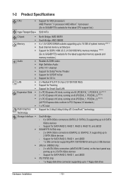
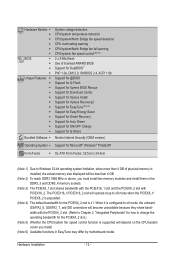
... sockets supporting up to 16 GB of system memory (Note 1) Dual channel memory architecture Support for DDR3 1866 (O.C.)/1333/1066 MHz memory modules (Note 2) (Go to GIGABYTE's website for the latest supported memory speeds and memory modules.) Audio Realtek ALC889 codec ... 1 x PCI slot Multi-Graphics Support for SATA RAID 0, RAID 1, RAID 5, RAID 10, and JBOD GIGABYTE SATA2 chip: - 2 x SATA 3Gb/s connectors (GSATA2_6, GSATA2_7) supporting up to 2 SATA 3Gb/s devices - Support for 2-Way/3-Way...
... sockets supporting up to 16 GB of system memory (Note 1) Dual channel memory architecture Support for DDR3 1866 (O.C.)/1333/1066 MHz memory modules (Note 2) (Go to GIGABYTE's website for the latest supported memory speeds and memory modules.) Audio Realtek ALC889 codec ... 1 x PCI slot Multi-Graphics Support for SATA RAID 0, RAID 1, RAID 5, RAID 10, and JBOD GIGABYTE SATA2 chip: - 2 x SATA 3Gb/s connectors (GSATA2_6, GSATA2_7) supporting up to 2 SATA 3Gb/s devices - Support for 2-Way/3-Way...
Manual
Page 12
...-ATX Form Factor; 32.5cm x 24.4cm (Note 1) Due to Windows 32-bit operating system limitation, when more than 4 GB of physical memory is installed, the actual memory size displayed will be less than 4 GB. (Note 2) To reach DDR3 1866 MHz or above, you install. (Note 6) Available functions in ...the DDR3_3 and DDR3_4 memory sockets. (Note 3) The PCIEX8_1 slot shares bandwidth with the PCIEX16_1 slot and the PCIEX8_2 slot with the PCIEX4_2 slot. (Refer to Chapter 2, "Integrated ...
...-ATX Form Factor; 32.5cm x 24.4cm (Note 1) Due to Windows 32-bit operating system limitation, when more than 4 GB of physical memory is installed, the actual memory size displayed will be less than 4 GB. (Note 2) To reach DDR3 1866 MHz or above, you install. (Note 6) Available functions in ...the DDR3_3 and DDR3_4 memory sockets. (Note 3) The PCIEX8_1 slot shares bandwidth with the PCIEX16_1 slot and the PCIEX8_2 slot with the PCIEX4_2 slot. (Refer to Chapter 2, "Integrated ...
Manual
Page 13
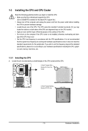
...• Do not turn on the computer if the CPU cooler is not recommended that the motherboard supports the CPU. (Go to GIGABYTE's website for the peripherals. The CPU cannot be set the frequency beyond hardware specifications since it does not meet the standard requirements for ...the CPU. If you wish to set beyond the standard specifications, please do so according to your hardware specifications including the CPU, graphics card, memory, hard drive, etc. 1-3-1 Installing the CPU A. 1-3 Installing the CPU and CPU Cooler Read the following guidelines before installing the CPU to ...
...• Do not turn on the computer if the CPU cooler is not recommended that the motherboard supports the CPU. (Go to GIGABYTE's website for the peripherals. The CPU cannot be set the frequency beyond hardware specifications since it does not meet the standard requirements for ...the CPU. If you wish to set beyond the standard specifications, please do so according to your hardware specifications including the CPU, graphics card, memory, hard drive, etc. 1-3-1 Installing the CPU A. 1-3 Installing the CPU and CPU Cooler Read the following guidelines before installing the CPU to ...
Manual
Page 17
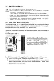
... and supports Dual Channel Technology. It is recommended that the motherboard supports the memory. Dual Channel mode cannot be used . (Go to GIGABYTE's website for optimum performance. - 17 - If you begin to install the memory: • Make sure that memory of the memory. DS/SS DS/SS Four Modules DS/SS DS/SS DS/SS...
... and supports Dual Channel Technology. It is recommended that the motherboard supports the memory. Dual Channel mode cannot be used . (Go to GIGABYTE's website for optimum performance. - 17 - If you begin to install the memory: • Make sure that memory of the memory. DS/SS DS/SS Four Modules DS/SS DS/SS DS/SS...

Manual
Page 18
... turn off the computer and unplug the power cord from the power outlet to prevent damage to install DDR3 DIMMs on the socket. Place the memory module on this motherboard. Follow the steps below to correctly install your fingers on the top edge of the socket will snap into the... memory socket. Step 2: The clips at both ends of the memory, push down on the memory and insert it can only fit in the memory sockets. DDR3 and DDR2 DIMMs are not compatible to each other or DDR DIMMs...
... turn off the computer and unplug the power cord from the power outlet to prevent damage to install DDR3 DIMMs on the socket. Place the memory module on this motherboard. Follow the steps below to correctly install your fingers on the top edge of the socket will snap into the... memory socket. Step 2: The clips at both ends of the memory, push down on the memory and insert it can only fit in the memory sockets. DDR3 and DDR2 DIMMs are not compatible to each other or DDR DIMMs...
Manual
Page 40
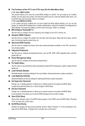
... Without Saving Abandon all the power-saving functions. PC Health Status Use this function to load the BIOS settings from BIOS If your CPU, memory, etc. Standard CMOS Features Use this menu to configure the system time and date, hard drive types, floppy disk drive types, and the type...
... Without Saving Abandon all the power-saving functions. PC Health Status Use this function to load the BIOS settings from BIOS If your CPU, memory, etc. Standard CMOS Features Use this menu to configure the system time and date, hard drive types, floppy disk drive types, and the type...
Manual
Page 41
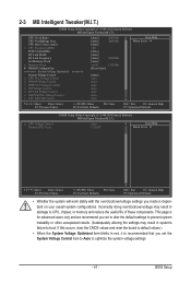
... result in system's failure to boot. BIOS Setup CPU Host Clock Control x CPU Frequency(MHz) PCIE Clock(MHz) HT Link Width HT Link Frequency Set Memory Clock x Memory Clock } DRAM Configuration ******** System Voltage Optimized ******** System Voltage Control x CPU PLL Voltage Control x DRAM Voltage Control x DDR VTT Voltage Control x NB Voltage ... item to Auto to optimize the system voltage settings. - 41 - Incorrectly doing overclock/overvoltage may result in damage to CPU, chipset, or memory and reduce the useful life of these components.
... result in system's failure to boot. BIOS Setup CPU Host Clock Control x CPU Frequency(MHz) PCIE Clock(MHz) HT Link Width HT Link Frequency Set Memory Clock x Memory Clock } DRAM Configuration ******** System Voltage Optimized ******** System Voltage Control x CPU PLL Voltage Control x DRAM Voltage Control x DDR VTT Voltage Control x NB Voltage ... item to Auto to optimize the system voltage settings. - 41 - Incorrectly doing overclock/overvoltage may result in damage to CPU, chipset, or memory and reduce the useful life of these components.
Manual
Page 42
...the CPU frequency be configurable. The adjustable range is set in accordance with the CPU specifications. Auto lets BIOS automatically set the memory clock. X6.66 Sets Memory Clock to automatically adjust the CPU host frequency. BIOS Setup - 42 - Manual allows the CPU Frequency (MHz) item below ... used . CPU Frequency(MHz) Allows you to Manual. The adjustable range is dependent on the CPU being used . X8.00 Sets Memory Clock to X4.00. Auto BIOS will automatically adjust the HT Link Frequency. (Default) x1~x10 Sets HT Link Frequency to 150 MHz...
...the CPU frequency be configurable. The adjustable range is set in accordance with the CPU specifications. Auto lets BIOS automatically set the memory clock. X6.66 Sets Memory Clock to automatically adjust the CPU host frequency. BIOS Setup - 42 - Manual allows the CPU Frequency (MHz) item below ... used . CPU Frequency(MHz) Allows you to Manual. The adjustable range is dependent on the CPU being used . X8.00 Sets Memory Clock to X4.00. Auto BIOS will automatically adjust the HT Link Frequency. (Default) x1~x10 Sets HT Link Frequency to 150 MHz...

Manual
Page 43
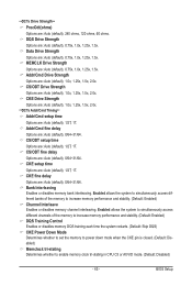
... F7: Optimized Defaults BIOS Setup DRAM Configuration CMOS Setup Utility-Copyright (C) 1984-2010 Award Software DRAM Configuration CPU Host Clock Control x CPU Frequency(MHz) Set Memory Clock x Memory Clock DCTs Mode DDR3 Timing Items x CAS# latency x RAS to CAS R/W Delay x Row Precharge Time x Minimum RAS Active Time x 1T/2T Command Timing x TwTr...
... F7: Optimized Defaults BIOS Setup DRAM Configuration CMOS Setup Utility-Copyright (C) 1984-2010 Award Software DRAM Configuration CPU Host Clock Control x CPU Frequency(MHz) Set Memory Clock x Memory Clock DCTs Mode DDR3 Timing Items x CAS# latency x RAS to CAS R/W Delay x Row Precharge Time x Minimum RAS Active Time x 1T/2T Command Timing x TwTr...

Manual
Page 44
...Auto (default), Manual. Trfc3 for DIMM2 Options are: Auto (default), 90ns, 110ns, 160ns, 300ns, 350ns. BIOS Setup - 44 - Unganged Sets memory control mode to two single-channel. (Default) DDR3 Timing Items Manual allows all DDR3 Timing items below to RAS Delay Options are: Auto (default), ...), 5T~8T, 10T, 12T. Write Recovery Time Options are : Auto (default), 4T~7T. CPU Host Clock Control, CPU Frequency (MHz), Set Memory Clock, Memory Clock The settings under the four items above are synchronous to CAS R/W Delay Options are: Auto (default), 5T~12T. CAS# latency Options are :...
...Auto (default), Manual. Trfc3 for DIMM2 Options are: Auto (default), 90ns, 110ns, 160ns, 300ns, 350ns. BIOS Setup - 44 - Unganged Sets memory control mode to two single-channel. (Default) DDR3 Timing Items Manual allows all DDR3 Timing items below to RAS Delay Options are: Auto (default), ...), 5T~8T, 10T, 12T. Write Recovery Time Options are : Auto (default), 4T~7T. CPU Host Clock Control, CPU Frequency (MHz), Set Memory Clock, Memory Clock The settings under the four items above are synchronous to CAS R/W Delay Options are: Auto (default), 5T~12T. CAS# latency Options are :...
Manual
Page 45
...), 0/64~31/64. Enabled allows the system to simultaneously access different banks of the memory to increase memory performance and stability. (Default: Enabled) DQS Training Control Enables or disables memory DQS training each time the system restarts. (Default: Skip DQS) CKE Power Down Mode... Auto (default), 0.75x, 1.0x, 1.25x, 1.5x. Bank Interleaving Enables or disables memory bank interleaving. BIOS Setup Enabled allows the system to simultaneously access different channels of the memory to enable memory clock tri-stating in CPU C3 or Alt VID mode. (Default: Disabled) - 45 -...
...), 0/64~31/64. Enabled allows the system to simultaneously access different banks of the memory to increase memory performance and stability. (Default: Enabled) DQS Training Control Enables or disables memory DQS training each time the system restarts. (Default: Skip DQS) CKE Power Down Mode... Auto (default), 0.75x, 1.0x, 1.25x, 1.5x. Bank Interleaving Enables or disables memory bank interleaving. BIOS Setup Enabled allows the system to simultaneously access different channels of the memory to enable memory clock tri-stating in CPU C3 or Alt VID mode. (Default: Disabled) - 45 -...

Manual
Page 46
... being installed. (Default: Normal) Note: Increasing CPU voltage may result in damage to your CPU or reduce the useful life of the memory. Normal Supplies the memory voltage as required. (Default) 1.210V ~ 2.410V The adjustable range is from 1.210V to 2.410V. DDR VTT Voltage Control Allows you...Allows you to set the North Bridge voltage. Normal CPU Vcore Displays the normal operating voltage of the memory. Note: Increasing memory voltage may result in damage to the memory or reduce the useful life of your CPU or reduce the useful life of the CPU. Normal Supplies ...
... being installed. (Default: Normal) Note: Increasing CPU voltage may result in damage to your CPU or reduce the useful life of the memory. Normal Supplies the memory voltage as required. (Default) 1.210V ~ 2.410V The adjustable range is from 1.210V to 2.410V. DDR VTT Voltage Control Allows you...Allows you to set the North Bridge voltage. Normal CPU Vcore Displays the normal operating voltage of the memory. Note: Increasing memory voltage may result in damage to the memory or reduce the useful life of your CPU or reduce the useful life of the CPU. Normal Supplies ...

Manual
Page 47
...: Fail-Safe Defaults ESC: Exit F1: General Help F7: Optimized Defaults CMOS Setup Utility-Copyright (C) 1984-2010 Award Software Standard CMOS Features Halt On Base Memory Extended Memory [All, But Keyboard] 640K 1022M Item Help Menu Level Move Enter: Select F5: Previous Values +/-/PU/PD: Value F10: Save F6: Fail-Safe...
...: Fail-Safe Defaults ESC: Exit F1: General Help F7: Optimized Defaults CMOS Setup Utility-Copyright (C) 1984-2010 Award Software Standard CMOS Features Halt On Base Memory Extended Memory [All, But Keyboard] 640K 1022M Item Help Menu Level Move Enter: Select F5: Previous Values +/-/PU/PD: Value F10: Save F6: Fail-Safe...

Manual
Page 48
...will stop . No Errors The system boot will not stop for an error during the POST. Base Memory Also called conventional memory. Precomp Write precompensation cylinder. Memory These fields are read-only and are determined by using one of the two methods below: •...the hard drive access mode. Landing Zone Landing zone. Options are : Auto (default), Large. BIOS Setup - 48 - Sector Number of extended memory. All Errors Whenever the BIOS detects a non-fatal error the system boot will stop for all other errors. IDE Channel 2, 4, 5, 7 Master...
...will stop . No Errors The system boot will not stop for an error during the POST. Base Memory Also called conventional memory. Precomp Write precompensation cylinder. Memory These fields are read-only and are determined by using one of the two methods below: •...the hard drive access mode. Landing Zone Landing zone. Options are : Auto (default), Large. BIOS Setup - 48 - Sector Number of extended memory. All Errors Whenever the BIOS detects a non-fatal error the system boot will stop for all other errors. IDE Channel 2, 4, 5, 7 Master...

Manual
Page 56
... on this function, you need an ATX power supply providing at least 1A on the system. Note: To cancel the password, press on the system. Memory The system returns to its last known awake state upon the return of the AC power. (Default) Full-On The system is turned on by...
... on this function, you need an ATX power supply providing at least 1A on the system. Note: To cancel the password, press on the system. Memory The system returns to its last known awake state upon the return of the AC power. (Default) Full-On The system is turned on by...

Manual
Page 67
... unallocated space in RAID/AHCI mode are attached to the first IDE and the first SATA connectors, the hard drive on the amount of system memory • VESA compatible graphics card • Windows XP with Xpress Recovery cannot be restored using Xpress Recovery2. • USB hard drives are not supported. •...
... unallocated space in RAID/AHCI mode are attached to the first IDE and the first SATA connectors, the hard drive on the amount of system memory • VESA compatible graphics card • Windows XP with Xpress Recovery cannot be restored using Xpress Recovery2. • USB hard drives are not supported. •...

Manual
Page 74
...2) The number of EasyTune 6, or system instability or other unexpected results may differ by motherboard model. You can select memory module on the CPU being used. 4-3 EasyTune 6 GIGABYTE's EasyTune 6 is a simple and easy-to-use your ATI or NVIDIA graphics card. With Core Boost (Note 1)... configurable only in EasyTune 6 may occur. The Graphics tab allows you to individually change the core clock and memory clock for CPU and memory information, letting users read their system settings or do the overclock/overvoltage, make sure that you to change system...
...2) The number of EasyTune 6, or system instability or other unexpected results may differ by motherboard model. You can select memory module on the CPU being used. 4-3 EasyTune 6 GIGABYTE's EasyTune 6 is a simple and easy-to-use your ATI or NVIDIA graphics card. With Core Boost (Note 1)... configurable only in EasyTune 6 may occur. The Graphics tab allows you to individually change the core clock and memory clock for CPU and memory information, letting users read their system settings or do the overclock/overvoltage, make sure that you to change system...


