Manual
Page 1
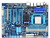
GA-890FXA-UD7 AM3 socket motherboard for AMD Phenom™ II processor/ AMD Athlon™ II processor User's Manual Rev. 2001 12ME-890FXA7-2001R
GA-890FXA-UD7 AM3 socket motherboard for AMD Phenom™ II processor/ AMD Athlon™ II processor User's Manual Rev. 2001 12ME-890FXA7-2001R
Manual
Page 2
Motherboard GA-890FXA-UD7 Mar. 29, 2010 Motherboard GA-890FXA-UD7 Mar. 29, 2010
Motherboard GA-890FXA-UD7 Mar. 29, 2010 Motherboard GA-890FXA-UD7 Mar. 29, 2010
Manual
Page 3
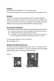
... their respective owners. Copyright © 2010 GIGA-BYTE TECHNOLOGY CO., LTD. Changes to use of GIGABYTE. The trademarks mentioned in this manual may be made by GIGABYTE without GIGABYTE's prior written permission. For example, "REV: 1.0" means the revision of the motherboard is the...Information in any form or by copyright laws and is 1.0. For product-related information, check on our website at: http://www.gigabyte.com.tw Identifying Your Motherboard Revision The revision number on our website. For detailed product information, carefully read or download the ...
... their respective owners. Copyright © 2010 GIGA-BYTE TECHNOLOGY CO., LTD. Changes to use of GIGABYTE. The trademarks mentioned in this manual may be made by GIGABYTE without GIGABYTE's prior written permission. For example, "REV: 1.0" means the revision of the motherboard is the...Information in any form or by copyright laws and is 1.0. For product-related information, check on our website at: http://www.gigabyte.com.tw Identifying Your Motherboard Revision The revision number on our website. For detailed product information, carefully read or download the ...
Manual
Page 4
Table of Contents Box Contents...6 Optional Items...6 GA-890FXA-UD7 Motherboard Layout 7 GA-890FXA-UD7 Motherboard Block Diagram 8 Chapter 1 Hardware Installation 9 1-1 Installation Precautions 9 1-2 Product Specifications 10 1-3 Installing the CPU and CPU Cooler 13 1-3-1 Installing the CPU 13 1-3-2 Installing the CPU ...
Table of Contents Box Contents...6 Optional Items...6 GA-890FXA-UD7 Motherboard Layout 7 GA-890FXA-UD7 Motherboard Block Diagram 8 Chapter 1 Hardware Installation 9 1-1 Installation Precautions 9 1-2 Product Specifications 10 1-3 Installing the CPU and CPU Cooler 13 1-3-1 Installing the CPU 13 1-3-2 Installing the CPU ...
Manual
Page 5
... 4-5 Q-Share...77 4-6 SMART Recovery 78 4-7 Auto Green...79 4-8 Teaming ...80 Chapter 5 Appendix...81 5-1 Configuring SATA Hard Drive(s 81 5-1-1 Configuring AMD SB850 SATA Controller 81 5-1-2 Configuring GIGABYTE SATA2/JMicron JMB362 SATA Controller 87 5-1-3 Making a SATA RAID/AHCI Driver Diskette 93 5-1-4 Installing the SATA RAID/AHCI Driver and Operating System 95 5-2 Configuring Audio...
... 4-5 Q-Share...77 4-6 SMART Recovery 78 4-7 Auto Green...79 4-8 Teaming ...80 Chapter 5 Appendix...81 5-1 Configuring SATA Hard Drive(s 81 5-1-1 Configuring AMD SB850 SATA Controller 81 5-1-2 Configuring GIGABYTE SATA2/JMicron JMB362 SATA Controller 87 5-1-3 Making a SATA RAID/AHCI Driver Diskette 93 5-1-4 Installing the SATA RAID/AHCI Driver and Operating System 95 5-2 Configuring Audio...
Manual
Page 6
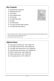
.... 12CF1-2SERPW-0*R) S/PDIF In cable (Part No. 12CR1-1SPDIN-0*R) COM port cable (Part No. 12CF1-1CM001-3*R) LPT port cable (Part No. 12CF1-1LP001-0*R) - 6 - Box Contents GA-890FXA-UD7 motherboard Motherboard driver disk User's Manual Quick Installation Guide One IDE cable Four SATA 3Gb/s cables I/O Shield One SATA bracket Two 2-Way CrossFireX bridge connectors...
.... 12CF1-2SERPW-0*R) S/PDIF In cable (Part No. 12CR1-1SPDIN-0*R) COM port cable (Part No. 12CF1-1CM001-3*R) LPT port cable (Part No. 12CF1-1LP001-0*R) - 6 - Box Contents GA-890FXA-UD7 motherboard Motherboard driver disk User's Manual Quick Installation Guide One IDE cable Four SATA 3Gb/s cables I/O Shield One SATA bracket Two 2-Way CrossFireX bridge connectors...
Manual
Page 7
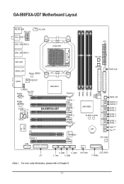
... DDR3_4 ATX PW_SW RST_SW PWR_FAN IDE FDD GIGABYTE SATA2 CMOS_SW AMD SB850 M_BIOS B_BIOS GSATA2_6 GSATA2_7 SATA3_4 SATA3_5 SATA3_2 SATA3_3 SATA3_0 SATA3_1 TSR1(Note) BAT TSL1(Note) SYS_FAN2 F_USB3 F_USB1 SYS_FAN1 CLR_CMOS LPT F_1394 F_USB2 F_PANEL (Note ) For error code information, please refer to Chapter 5. - 7 - GA-890FXA-UD7 Motherboard Layout KB_MS_USB ATX_12V RCA_SPDIF USB_1394_ESATA_2...
... DDR3_4 ATX PW_SW RST_SW PWR_FAN IDE FDD GIGABYTE SATA2 CMOS_SW AMD SB850 M_BIOS B_BIOS GSATA2_6 GSATA2_7 SATA3_4 SATA3_5 SATA3_2 SATA3_3 SATA3_0 SATA3_1 TSR1(Note) BAT TSL1(Note) SYS_FAN2 F_USB3 F_USB1 SYS_FAN1 CLR_CMOS LPT F_1394 F_USB2 F_PANEL (Note ) For error code information, please refer to Chapter 5. - 7 - GA-890FXA-UD7 Motherboard Layout KB_MS_USB ATX_12V RCA_SPDIF USB_1394_ESATA_2...
Manual
Page 8
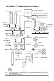
GA-890FXA-UD7 Motherboard Block Diagram 4 PCI Express x8 2 PCI Express x16 1 PCI Express x4 or PCIe CLK (100 MHz) PCI Express x8 x16 Bus Switch x4 x1 ... MHz (Note 1) Dual Channel Memory Hyper Transport 3.0 1 PCI Express x4 AMD 890FX 1 PCI Express x1 or 2 SATA 3Gb/s ATA-133/100/66/ 33 IDE Channel GIGABYTE x4 x1 SATA2 Switch PCIe CLK (100 MHz) 14 USB 2.0/1.1 (Note 2) PCI Express Bus x1 x1 PCIe CLK (100 MHz) Realtek Realtek RTL8111D RTL8111D RJ45...
GA-890FXA-UD7 Motherboard Block Diagram 4 PCI Express x8 2 PCI Express x16 1 PCI Express x4 or PCIe CLK (100 MHz) PCI Express x8 x16 Bus Switch x4 x1 ... MHz (Note 1) Dual Channel Memory Hyper Transport 3.0 1 PCI Express x4 AMD 890FX 1 PCI Express x1 or 2 SATA 3Gb/s ATA-133/100/66/ 33 IDE Channel GIGABYTE x4 x1 SATA2 Switch PCIe CLK (100 MHz) 14 USB 2.0/1.1 (Note 2) PCI Express Bus x1 x1 PCIe CLK (100 MHz) Realtek Realtek RTL8111D RTL8111D RJ45...

Manual
Page 9
These stickers are required for warranty validation. • Always remove the AC power by your hands dry and first touch a metal object to eliminate static electricity. • Prior to installing the motherboard, please have a problem related to wear an electrostatic discharge (ESD) wrist strap when handling electronic com- ponents such as a result of your hardware components are connected. • To prevent damage to the motherboard, do not allow screws to come in a high-temperature environment. • Turning on the motherboard, make sure they are uncertain about any metal ...
These stickers are required for warranty validation. • Always remove the AC power by your hands dry and first touch a metal object to eliminate static electricity. • Prior to installing the motherboard, please have a problem related to wear an electrostatic discharge (ESD) wrist strap when handling electronic com- ponents such as a result of your hardware components are connected. • To prevent damage to the motherboard, do not allow screws to come in a high-temperature environment. • Turning on the motherboard, make sure they are uncertain about any metal ...
Manual
Page 10
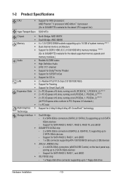
... - 1-2 Product Specifications CPU Support for AM3 processors: AMD Phenom™ II processor/ AMD Athlon™ II processor (Go to GIGABYTE's website for the latest CPU support list.) Hyper Transport Bus 5200 MT/s Chipset North Bridge: AMD 890FX ...Note 1) Dual channel memory architecture Support for DDR3 1866 (O.C.)/1333/1066 MHz memory modules (Note 2) (Go to GIGABYTE's website for the latest supported memory speeds and memory modules.) Audio Realtek ALC889 codec High Definition Audio ...
... - 1-2 Product Specifications CPU Support for AM3 processors: AMD Phenom™ II processor/ AMD Athlon™ II processor (Go to GIGABYTE's website for the latest CPU support list.) Hyper Transport Bus 5200 MT/s Chipset North Bridge: AMD 890FX ...Note 1) Dual channel memory architecture Support for DDR3 1866 (O.C.)/1333/1066 MHz memory modules (Note 2) (Go to GIGABYTE's website for the latest supported memory speeds and memory modules.) Audio Realtek ALC889 codec High Definition Audio ...

Manual
Page 11
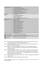
TSB43AB23 chip - USB South Bridge - Hardware Installation Up to the internal IEEE 1394a header) Internal w 1 x 24-pin ATX main power connector Connectors w 1 x 8-pin ATX 12V power connector w 1 x floppy disk drive connector w 1 x IDE connector w 6 x SATA 6Gb/s connectors w 2 x SATA 3Gb/s connectors w 1 x CPU fan header w 2 x system fan headers w 1 x North Bridge fan header w 1 x power fan header w 1 x front panel header w 1 x front panel audio header w 1 x CD In connector w 1 x S/...
TSB43AB23 chip - USB South Bridge - Hardware Installation Up to the internal IEEE 1394a header) Internal w 1 x 24-pin ATX main power connector Connectors w 1 x 8-pin ATX 12V power connector w 1 x floppy disk drive connector w 1 x IDE connector w 6 x SATA 6Gb/s connectors w 2 x SATA 3Gb/s connectors w 1 x CPU fan header w 2 x system fan headers w 1 x North Bridge fan header w 1 x power fan header w 1 x front panel header w 1 x front panel audio header w 1 x CD In connector w 1 x S/...
Manual
Page 12
The PCIEX16_1/PCIEX16_2 slot will operate at up to x8 mode when the PCIEX8_1/ PCIEX8_2 is populated. (Note 4) The default bandwidth for the PCIEX4_2 slot is x1. When it is configured to x4 mode, the onboard GSATA2_6, GSATA2_7, and IDE connectors will become unavailable because they share band width with the PCIEX4_2 slot. (Refer to Chapter 2, "Integrated Peripherals" for how to change the operating bandwidth for the PCIEX4_2 slot.) (Note 5) Whether the CPU/system fan speed control function is supported will depend on the CPU/system cooler you must install two memory modules and ...
The PCIEX16_1/PCIEX16_2 slot will operate at up to x8 mode when the PCIEX8_1/ PCIEX8_2 is populated. (Note 4) The default bandwidth for the PCIEX4_2 slot is x1. When it is configured to x4 mode, the onboard GSATA2_6, GSATA2_7, and IDE connectors will become unavailable because they share band width with the PCIEX4_2 slot. (Refer to Chapter 2, "Integrated Peripherals" for how to change the operating bandwidth for the PCIEX4_2 slot.) (Note 5) Whether the CPU/system fan speed control function is supported will depend on the CPU/system cooler you must install two memory modules and ...
Manual
Page 13
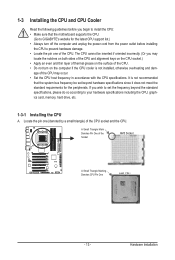
... latest CPU support list.) • Always turn on the computer if the CPU cooler is not recommended that the motherboard supports the CPU. (Go to GIGABYTE's website for the peripherals. A Small Triangle Mark Denotes Pin One of the CPU socket and the CPU.
... latest CPU support list.) • Always turn on the computer if the CPU cooler is not recommended that the motherboard supports the CPU. (Go to GIGABYTE's website for the peripherals. A Small Triangle Mark Denotes Pin One of the CPU socket and the CPU.

Manual
Page 14
Adjust the CPU orientation if this occurs. Make sure that the CPU pins fit perfectly into the fully locked position. Hardware Installation - 14 - CPU Socket Locking Lever Step 1: Completely lift up the CPU socket locking lever. The CPU cannot fit in if oriented incorrectly. Once the CPU is positioned into its socket, place one (small triangle marking) with the triangle mark on the middle of the CPU, lowering the locking lever and latching it into their holes. Follow the steps below to correctly install the CPU into the motherboard CPU socket. • Before installing ...
Adjust the CPU orientation if this occurs. Make sure that the CPU pins fit perfectly into the fully locked position. Hardware Installation - 14 - CPU Socket Locking Lever Step 1: Completely lift up the CPU socket locking lever. The CPU cannot fit in if oriented incorrectly. Once the CPU is positioned into its socket, place one (small triangle marking) with the triangle mark on the middle of the CPU, lowering the locking lever and latching it into their holes. Follow the steps below to correctly install the CPU into the motherboard CPU socket. • Before installing ...

Manual
Page 15
... on the CPU. 1-3-2 Installing the CPU Cooler Follow the steps below to correctly install the CPU cooler on the CPU. (The following procedure uses the GIGABYTE cooler as the picture above shows) to lock into place. (Refer to your CPU cooler installation manual for instructions on installing the cooler.) Step 5: Finally...
... on the CPU. 1-3-2 Installing the CPU Cooler Follow the steps below to correctly install the CPU cooler on the CPU. (The following procedure uses the GIGABYTE cooler as the picture above shows) to lock into place. (Refer to your CPU cooler installation manual for instructions on installing the cooler.) Step 5: Finally...

Manual
Page 16
Step 2: Apply an even thin layer of thermal grease on the surface of the Hybrid SilentPipe module atop North Bridge's heatsink as shown. Hardware Installation - 16 - After connecting the tubes, make sure that the tubes are attached to complete the installation. (Note) For the waterblock, we recommend using tubes with inner diameter of 7.5mm and outer diameter of 10mm. The components received may vary in appearance from the waterblock on North Bridge's heatsink and then remove the waterblock. Step 3: Place the heatsink of the heatsink. Thermal grease Hybrid Silent-Pipe ...
Step 2: Apply an even thin layer of thermal grease on the surface of the Hybrid SilentPipe module atop North Bridge's heatsink as shown. Hardware Installation - 16 - After connecting the tubes, make sure that the tubes are attached to complete the installation. (Note) For the waterblock, we recommend using tubes with inner diameter of 7.5mm and outer diameter of 10mm. The components received may vary in appearance from the waterblock on North Bridge's heatsink and then remove the waterblock. Step 3: Place the heatsink of the heatsink. Thermal grease Hybrid Silent-Pipe ...
Manual
Page 17
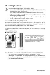
... mode with two or four memory modules, it is installed, the BIOS will double the original memory bandwidth. A memory module can be used . (Go to GIGABYTE's website for optimum performance. - 17 - Hardware Installation DS/SS DS/SS Four Modules DS/SS DS/SS DS/SS DS/SS (SS=Single-Sided, DS...
... mode with two or four memory modules, it is installed, the BIOS will double the original memory bandwidth. A memory module can be used . (Go to GIGABYTE's website for optimum performance. - 17 - Hardware Installation DS/SS DS/SS Four Modules DS/SS DS/SS DS/SS DS/SS (SS=Single-Sided, DS...

Manual
Page 18
Step 1: Note the orientation of the memory, push down on the top edge of the memory module. Spread the retaining clips at both ends of the socket will snap into the memory socket. 1-5-2 Installing a Memory Before installing a memory module, make sure to turn off the computer and unplug the power cord from the power outlet to prevent damage to install DDR3 DIMMs on the socket. Hardware Installation - 18 - Follow the steps below to correctly install your memory modules in the picture on the left, place your fingers on the memory and insert it can only fit in one direction....
Step 1: Note the orientation of the memory, push down on the top edge of the memory module. Spread the retaining clips at both ends of the socket will snap into the memory socket. 1-5-2 Installing a Memory Before installing a memory module, make sure to turn off the computer and unplug the power cord from the power outlet to prevent damage to install DDR3 DIMMs on the socket. Hardware Installation - 18 - Follow the steps below to correctly install your memory modules in the picture on the left, place your fingers on the memory and insert it can only fit in one direction....
Manual
Page 19
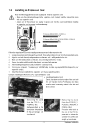
PCI Express x16 Slot (PCIEX16_1/PCIEX16_2) PCI Express x16 Slot (PCIEX8_1/PCIEX8_2/PCIEX4_1/PCIEX4_2) PCI Slot Follow the steps below to correctly install your computer. Secure the card's metal bracket to the chassis back panel with the expansion card in the slot and does not rock. • Removing the Card from the slot. Install the driver provided with a screw. 5. After installing all expansion cards, replace the chassis cover(s). 6. Align the card with your operating system. Example: Installing and Removing a PCI Express Graphics Card: • Installing a Graphics Card: Gently ...
PCI Express x16 Slot (PCIEX16_1/PCIEX16_2) PCI Express x16 Slot (PCIEX8_1/PCIEX8_2/PCIEX4_1/PCIEX4_2) PCI Slot Follow the steps below to correctly install your computer. Secure the card's metal bracket to the chassis back panel with the expansion card in the slot and does not rock. • Removing the Card from the slot. Install the driver provided with a screw. 5. After installing all expansion cards, replace the chassis cover(s). 6. Align the card with your operating system. Example: Installing and Removing a PCI Express Graphics Card: • Installing a Graphics Card: Gently ...
Manual
Page 20
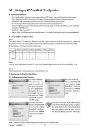
Step 3: Plug the display cable into the graphics card on the PCI Express x16 slots. Browse to apply. Procedure and driver screen for more information about enabling CrossFireX technology. (Note) The bridge connectors may differ by graphics cards. 1-7 Setting up ATI CrossFireX™ Configuration A. A CrossFireX-supported motherboard with two/three/four cards. Connecting the Graphics Cards Step 1: Observe the steps in "1-6 Installing an Expansion Card" and install two/three/four CrossFireX-ready graphics cards on the PCIEX16_1 slot. Configuring the Graphics Card Driver...
Step 3: Plug the display cable into the graphics card on the PCI Express x16 slots. Browse to apply. Procedure and driver screen for more information about enabling CrossFireX technology. (Note) The bridge connectors may differ by graphics cards. 1-7 Setting up ATI CrossFireX™ Configuration A. A CrossFireX-supported motherboard with two/three/four cards. Connecting the Graphics Cards Step 1: Observe the steps in "1-6 Installing an Expansion Card" and install two/three/four CrossFireX-ready graphics cards on the PCIEX16_1 slot. Configuring the Graphics Card Driver...
