
Manual
Page 4
Table of Contents Box Contents...6 Optional Items...6 GA-880GM-D2H Motherboard Layout 7 GA-880GM-D2H Motherboard Block Diagram 8 Chapter 1 Hardware Installation 9 1-1 Installation Precautions 9 1-2 Product Specifications 10 1-3 Installing the CPU and CPU Cooler 13 1-3-1 Installing the CPU 13 1-3-2 Installing the CPU Cooler 15 1-4 Installing the Memory 16 1-4-1 Dual Channel Memory Configuration 16 1-4-2 Installing a Memory 17 1-5 Installing an Expansion Card 18 1-6 Back...
Table of Contents Box Contents...6 Optional Items...6 GA-880GM-D2H Motherboard Layout 7 GA-880GM-D2H Motherboard Block Diagram 8 Chapter 1 Hardware Installation 9 1-1 Installation Precautions 9 1-2 Product Specifications 10 1-3 Installing the CPU and CPU Cooler 13 1-3-1 Installing the CPU 13 1-3-2 Installing the CPU Cooler 15 1-4 Installing the Memory 16 1-4-1 Dual Channel Memory Configuration 16 1-4-2 Installing a Memory 17 1-5 Installing an Expansion Card 18 1-6 Back...

Manual
Page 8
GA-880GM-D2H Motherboard Block Diagram PCIe CLK (100 MHz) AM3 CPU CPU CLK+/- (200 MHz) DDR3 1666(O.C.)/1333/1066 MHz Dual Channel Memory 1 PCI Express x16 Hyper Transport Bus PCI Express x16 PCI Express Bus x1 PCIe CLK (100 MHz) 1 PCI Express x1 Realtek RTL8111D/E RJ45 LAN AMD ...
GA-880GM-D2H Motherboard Block Diagram PCIe CLK (100 MHz) AM3 CPU CPU CLK+/- (200 MHz) DDR3 1666(O.C.)/1333/1066 MHz Dual Channel Memory 1 PCI Express x16 Hyper Transport Bus PCI Express x16 PCI Express Bus x1 PCIe CLK (100 MHz) 1 PCI Express x1 Realtek RTL8111D/E RJ45 LAN AMD ...

Manual
Page 9
...-temperature environment. • Turning on the computer power during the installation process can lead to damage to system components as well as a motherboard, CPU or memory. Prior to installation, carefully read the user's manual and follow these procedures: • Prior to installation, do not have an ESD wrist strap, keep your...
...-temperature environment. • Turning on the computer power during the installation process can lead to damage to system components as well as a motherboard, CPU or memory. Prior to installation, carefully read the user's manual and follow these procedures: • Prior to installation, do not have an ESD wrist strap, keep your...

Manual
Page 10
...; II processor/ AMD Athlon™ II processor (Go to GIGABYTE's website for the latest CPU support list.) Hyper Transport Bus 5200 MT/s Chipset Memory Onboard Graphics Audio ... x 1.5V DDR3 DIMM sockets supporting up to 8 GB of system memory (Note 1) Dual channel memory architecture Support for DDR3 1666(O.C.)/1333/1066 MHz memory modules (Go to GIGABYTE's website for the latest supported memory speeds and memory modules.) Integrated in the North Bridge: - 1 x D-Sub port...
...; II processor/ AMD Athlon™ II processor (Go to GIGABYTE's website for the latest CPU support list.) Hyper Transport Bus 5200 MT/s Chipset Memory Onboard Graphics Audio ... x 1.5V DDR3 DIMM sockets supporting up to 8 GB of system memory (Note 1) Dual channel memory architecture Support for DDR3 1666(O.C.)/1333/1066 MHz memory modules (Go to GIGABYTE's website for the latest supported memory speeds and memory modules.) Integrated in the North Bridge: - 1 x D-Sub port...

Manual
Page 12
... w Micro ATX Form Factor; 24.4cm x 22.0cm (Note 1) Due to Windows 32-bit operating system limitation, when more than 4 GB of physical memory is installed, the actual memory size displayed will be less than 4 GB. (Note 2) The DVI-D port does not support D-Sub connection by adapter. (Note 3) You can use only...
... w Micro ATX Form Factor; 24.4cm x 22.0cm (Note 1) Due to Windows 32-bit operating system limitation, when more than 4 GB of physical memory is installed, the actual memory size displayed will be less than 4 GB. (Note 2) The DVI-D port does not support D-Sub connection by adapter. (Note 3) You can use only...

Manual
Page 13
... if oriented incorrectly. (Or you wish to set beyond the standard specifications, please do so according to your hardware specifications including the CPU, graphics card, memory, hard drive, etc. 1-3-1 Installing the CPU A. If you may occur. • Set the CPU host frequency in accordance with the CPU specifications.... layer of thermal grease on the computer if the CPU cooler is not recommended that the motherboard supports the CPU. (Go to GIGABYTE's website for the peripherals. Locate the pin one of the Socket AM3 Socket A Small Triangle Marking Denotes CPU Pin One AM3 CPU - 13...
... if oriented incorrectly. (Or you wish to set beyond the standard specifications, please do so according to your hardware specifications including the CPU, graphics card, memory, hard drive, etc. 1-3-1 Installing the CPU A. If you may occur. • Set the CPU host frequency in accordance with the CPU specifications.... layer of thermal grease on the computer if the CPU cooler is not recommended that the motherboard supports the CPU. (Go to GIGABYTE's website for the peripherals. Locate the pin one of the Socket AM3 Socket A Small Triangle Marking Denotes CPU Pin One AM3 CPU - 13...

Manual
Page 16
... capacity, brand, speed, and chips be used . (Go to GIGABYTE's website for the latest supported memory speeds and memory modules.) • Always turn off the computer and unplug the power cord from the power outlet before installing the memory to prevent hardware damage. • Memory modules have a foolproof design. When enabling Dual Channel mode with...
... capacity, brand, speed, and chips be used . (Go to GIGABYTE's website for the latest supported memory speeds and memory modules.) • Always turn off the computer and unplug the power cord from the power outlet before installing the memory to prevent hardware damage. • Memory modules have a foolproof design. When enabling Dual Channel mode with...

Manual
Page 17
... As indicated in the picture on the left, place your memory modules in one direction. Step 1: Note the orientation of the memory socket. Notch DDR3 DIMM A DDR3 memory module has a notch, so it vertically into place when the memory module is securely inserted. - 17 - Follow the steps ... will snap into the memory socket. Step 2: The clips at both ends of the memory, push down on the memory and insert it can only fit in the memory sockets. Spread the retaining clips at both ends of the memory module. 1-4-2 Installing a Memory Before installing a memory module, make sure to...
... As indicated in the picture on the left, place your memory modules in one direction. Step 1: Note the orientation of the memory socket. Notch DDR3 DIMM A DDR3 memory module has a notch, so it vertically into place when the memory module is securely inserted. - 17 - Follow the steps ... will snap into the memory socket. Step 2: The clips at both ends of the memory, push down on the memory and insert it can only fit in the memory sockets. Spread the retaining clips at both ends of the memory module. 1-4-2 Installing a Memory Before installing a memory module, make sure to...

Manual
Page 20
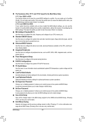
... in devices such as an optical drive, walkman, etc. The table below . • CPU: AMD Phenom™ X3 processor or above • Memory: Two 1 GB DDR3 1066 MHz memory modules with dual channel mode enabled • BIOS Setup: At least 256 MB of UMA Frame Buffer Size (refer to 1 Gbps data rate...
... in devices such as an optical drive, walkman, etc. The table below . • CPU: AMD Phenom™ X3 processor or above • Memory: Two 1 GB DDR3 1066 MHz memory modules with dual channel mode enabled • BIOS Setup: At least 256 MB of UMA Frame Buffer Size (refer to 1 Gbps data rate...
Manual
Page 34
... profile. First enter the profile name (to erase the default profile name, use this function to load the BIOS settings from BIOS If your CPU, memory, etc. Standard CMOS Features Use this menu to configure the system time and date, hard drive types, floppy disk drive types, and the type...
... profile. First enter the profile name (to erase the default profile name, use this function to load the BIOS settings from BIOS If your CPU, memory, etc. Standard CMOS Features Use this menu to configure the system time and date, hard drive types, floppy disk drive types, and the type...
Manual
Page 35
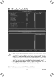
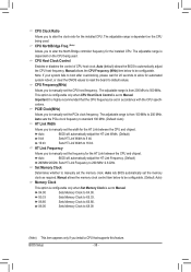
... Configuration CPU Clock Ratio CPU NorthBridge Freq.(Note) CPU Host Clock Control x CPU Frequency(MHz) PCIE Clock(MHz) HT Link Width HT Link Frequency Set Memory Clock x Memory Clock } DRAM Configuration ******** System Voltage Optimized ******** System Voltage Control x DDR3 Voltage Control x NorthBridge Volt Control x SouthBridge Volt Control x CPU NB VID Control x ... only and we recommend you install a CPU that supports this occurs, clear the CMOS values and reset the board to CPU, chipset, or memory and reduce the useful life of these components.
... Configuration CPU Clock Ratio CPU NorthBridge Freq.(Note) CPU Host Clock Control x CPU Frequency(MHz) PCIE Clock(MHz) HT Link Width HT Link Frequency Set Memory Clock x Memory Clock } DRAM Configuration ******** System Voltage Optimized ******** System Voltage Control x DDR3 Voltage Control x NorthBridge Volt Control x SouthBridge Volt Control x CPU NB VID Control x ... only and we recommend you install a CPU that supports this occurs, clear the CMOS values and reset the board to CPU, chipset, or memory and reduce the useful life of these components.
Manual
Page 37
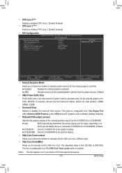
... determine whether to manually set the VGA Core clock. (Default: Auto) VGA Core Clock(MHz) Allows you to manually set to allocate system memory for output, depending on to 2000 MHz. This item is configurable only if the VGA Core Clock control option is enabled. (Note) This ...item appears only if you install a CPU that supports this memory for the onboard graphics controller. UMA Allocates memory for the onboard graphics controller from the system memory. (Default) UMA Frame Buffer Size Frame buffer size is the total amount of the onboard graphics ...
... determine whether to manually set the VGA Core clock. (Default: Auto) VGA Core Clock(MHz) Allows you to manually set to allocate system memory for output, depending on to 2000 MHz. This item is configurable only if the VGA Core Clock control option is enabled. (Note) This ...item appears only if you install a CPU that supports this memory for the onboard graphics controller. UMA Allocates memory for the onboard graphics controller from the system memory. (Default) UMA Frame Buffer Size Frame buffer size is the total amount of the onboard graphics ...
Manual
Page 38
... frequency. Important It is highly recommended that supports this feature. PCIE Clock(MHz) Allows you to manually set the CPU host frequency. X4.00 Sets Memory Clock to X6.66. BIOS Setup - 38 - CPU Clock Ratio Allows you to manually set the width for the HT Link between the CPU and... overclocking, please wait for 20 seconds to allow for the installed CPU. The adjustable range is from 100 MHz to be configurable. Manual allows the memory clock control item below to 200 MHz. The adjustable range is set to alter the clock ratio for the HT Link between the CPU and...
... frequency. Important It is highly recommended that supports this feature. PCIE Clock(MHz) Allows you to manually set the CPU host frequency. X4.00 Sets Memory Clock to X6.66. BIOS Setup - 38 - CPU Clock Ratio Allows you to manually set the width for the HT Link between the CPU and... overclocking, please wait for 20 seconds to allow for the installed CPU. The adjustable range is from 100 MHz to be configurable. Manual allows the memory clock control item below to 200 MHz. The adjustable range is set to alter the clock ratio for the HT Link between the CPU and...

Manual
Page 39
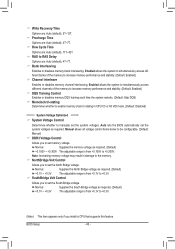
... Active Time Options are: Auto (default), 15T~30T. 1T/2T Command Timing Options are : Auto (default), Manual. BIOS Setup Unganged Sets memory control mode to two single-channel. (Default) DDR3 Timing Items Manual allows all DDR3 Timing items below to single dual-channel. CAS# latency ...Options are : Auto (default), 4T~7T. TwTr Command Delay Options are : Auto (default), 4T~12T. Ganged Sets memory control mode to be configurable. Trfc2 for DIMM2 x Write Recovery Time x Precharge Time x Row Cycle Time x RAS to RAS Delay Bank Interleaving ...
... Active Time Options are: Auto (default), 15T~30T. 1T/2T Command Timing Options are : Auto (default), Manual. BIOS Setup Unganged Sets memory control mode to two single-channel. (Default) DDR3 Timing Items Manual allows all DDR3 Timing items below to single dual-channel. CAS# latency ...Options are : Auto (default), 4T~7T. TwTr Command Delay Options are : Auto (default), 4T~12T. Ganged Sets memory control mode to be configurable. Trfc2 for DIMM2 x Write Recovery Time x Precharge Time x Row Cycle Time x RAS to RAS Delay Bank Interleaving ...
Manual
Page 40
... allows all voltage control items below to be configurable. (Default: Manual) DDR3 Voltage Control Allows you to increase memory performance and stability. (Default: Enabled) Channel interleave Enables or disables memory channel interleaving. Note: Increasing memory voltage may result in CPU C3 or Alt VID mode. (Default: Disabled) ******** System Voltage Optimized ******** System Voltage Control...
... allows all voltage control items below to be configurable. (Default: Manual) DDR3 Voltage Control Allows you to increase memory performance and stability. (Default: Enabled) Channel interleave Enables or disables memory channel interleaving. Note: Increasing memory voltage may result in CPU C3 or Alt VID mode. (Default: Disabled) ******** System Voltage Optimized ******** System Voltage Control...

Manual
Page 42
... } IDE Channel 3 Master } IDE Channel 3 Slave [None] [None] [None] [None] [None] [None] Drive A Floppy 3 Mode Support [1.44M, 3.5"] [Disabled] Halt On [All, But Keyboard] Base Memory Extended Memory 640K 1790M Move Enter: Select F5: Previous Values +/-/PU/PD: Value F10: Save F6: Fail-Safe Defaults ESC: Exit F1: General Help F7: Optimized Defaults...
... } IDE Channel 3 Master } IDE Channel 3 Slave [None] [None] [None] [None] [None] [None] Drive A Floppy 3 Mode Support [1.44M, 3.5"] [Disabled] Halt On [All, But Keyboard] Base Memory Extended Memory 640K 1790M Move Enter: Select F5: Previous Values +/-/PU/PD: Value F10: Save F6: Fail-Safe Defaults ESC: Exit F1: General Help F7: Optimized Defaults...

Manual
Page 43
...type of the currently installed hard drive. Sector Number of extended memory. - 43 - Memory These fields are read-only and are : None, 360K/5.25", 1.2M/5.25", 720K/3.5", 1.44M/3.5", 2.88M/3.5". Extended Memory The amount of sectors. Precomp Write precompensation cylinder. Options are... standard floppy disk drive. Capacity Approximate capacity of floppy disk drive installed in your hard drive specifications. Base Memory Also called conventional memory. Typically, 640 KB will not stop for a keyboard error but stop for the MS-DOS operating system....
...type of the currently installed hard drive. Sector Number of extended memory. - 43 - Memory These fields are read-only and are : None, 360K/5.25", 1.2M/5.25", 720K/3.5", 1.44M/3.5", 2.88M/3.5". Extended Memory The amount of sectors. Precomp Write precompensation cylinder. Options are... standard floppy disk drive. Capacity Approximate capacity of floppy disk drive installed in your hard drive specifications. Base Memory Also called conventional memory. Typically, 640 KB will not stop for a keyboard error but stop for the MS-DOS operating system....

Manual
Page 50
... removal of Month): Turn on the system, enter the password and press . Power On By Keyboard Allows the system to be turned on the system. Memory The system returns to clear the password settings. To turn on by a PS/2 mouse wake-up event. Resume Time (hh: mm: ss): Set the time...
... removal of Month): Turn on the system, enter the password and press . Power On By Keyboard Allows the system to be turned on the system. Memory The system returns to clear the password settings. To turn on by a PS/2 mouse wake-up event. Resume Time (hh: mm: ss): Set the time...
Manual
Page 61
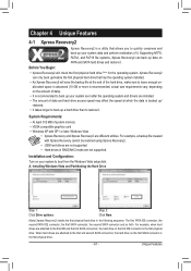
... at which the data is backed up/ restored. • It takes longer to back up data on your system data and perform restoration of system memory • VESA compatible graphics card • Windows XP with Xpress Recovery cannot be restored using Xpress Recovery2. • USB hard drives are attached to the...
... at which the data is backed up/ restored. • It takes longer to back up data on your system data and perform restoration of system memory • VESA compatible graphics card • Windows XP with Xpress Recovery cannot be restored using Xpress Recovery2. • USB hard drives are attached to the...

Manual
Page 68
...buzzer or use your ATI or NVIDIA graphics card. Before you do overclock/overvoltage in the notification area. You can select memory module on the CPU temperature thresholds you fully know each function of CPU cores that can choose the alert sound from a... the sliders. • Easy Boost is an easy-to-use auto-overclocking function (Note 1). Unique Features - 68 - 4-3 EasyTune 6 GIGABYTE's EasyTune 6 is a simple and easy-to-use interface that allows users to fine-tune their system-related information without the need to install...
...buzzer or use your ATI or NVIDIA graphics card. Before you do overclock/overvoltage in the notification area. You can select memory module on the CPU temperature thresholds you fully know each function of CPU cores that can choose the alert sound from a... the sliders. • Easy Boost is an easy-to-use auto-overclocking function (Note 1). Unique Features - 68 - 4-3 EasyTune 6 GIGABYTE's EasyTune 6 is a simple and easy-to-use interface that allows users to fine-tune their system-related information without the need to install...


