
Manual
Page 1
GA-7TCSV-RH Dual Xeon Processor Motherboard USER'S MANUAL XeonTM Processor Motherboard Rev. 1001 * The WEEE marking on the product indicates this product must not be disposed of with user's other household waste and must be handed over to a designated collection point for the recycling of waste electrical and electronic equipment!! * The WEEE marking applies only in European Union's member states.
GA-7TCSV-RH Dual Xeon Processor Motherboard USER'S MANUAL XeonTM Processor Motherboard Rev. 1001 * The WEEE marking on the product indicates this product must not be disposed of with user's other household waste and must be handed over to a designated collection point for the recycling of waste electrical and electronic equipment!! * The WEEE marking applies only in European Union's member states.
Manual
Page 2
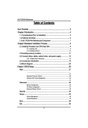
... of Contents Item Checklist 3 Chapter 1Introduction 4 1.1.Considerations Prior to Installation 4 1.2.Features Summary 5 1.3.GA-7TCSV-RH Motherboard Component 7 Chapter 2Hardware Installation Process 9 2.1.Installing Processor and CPU Haet Sink 9 2.1.1.Installing CPU ...9 2.1.2.Installing Heat Sink 10 2.2.Installing memory modules 11 2.3.Connect ribbon cables, cabinet ...
... of Contents Item Checklist 3 Chapter 1Introduction 4 1.1.Considerations Prior to Installation 4 1.2.Features Summary 5 1.3.GA-7TCSV-RH Motherboard Component 7 Chapter 2Hardware Installation Process 9 2.1.Installing Processor and CPU Haet Sink 9 2.1.1.Installing CPU ...9 2.1.2.Installing Heat Sink 10 2.2.Installing memory modules 11 2.3.Connect ribbon cables, cabinet ...

Manual
Page 3
English GA-7TCSV-RH Motherboard Item Checklist The GA-7TCSV-RH motherboard Serial ATA cable x 6 IDE (ATA100 ) cable x 1 / Floppy cable x 1 I/O Shield Kit CD for motherboard driver & utility Power cable x 4 GA-7TCSV-RH quick reference guide * The items listed above are for reference only, and are subject to change without notice. 3
English GA-7TCSV-RH Motherboard Item Checklist The GA-7TCSV-RH motherboard Serial ATA cable x 6 IDE (ATA100 ) cable x 1 / Floppy cable x 1 I/O Shield Kit CD for motherboard driver & utility Power cable x 4 GA-7TCSV-RH quick reference guide * The items listed above are for reference only, and are subject to change without notice. 3

Manual
Page 4
... the user. 8. Thus, prior to be an unofficial Gigabyte product. 4 Please make sure there are uncertain about any installation steps or have these items on an uneven surface. 7. Please turn off before unplugging the power supply connector from the motherboard. When handling the motherboard, avoid touching any hardware, please first carefully read the...
... the user. 8. Thus, prior to be an unofficial Gigabyte product. 4 Please make sure there are uncertain about any installation steps or have these items on an uneven surface. 7. Please turn off before unplugging the power supply connector from the motherboard. When handling the motherboard, avoid touching any hardware, please first carefully read the...
Manual
Page 5
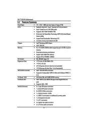
English GA-7TCSV-RH Motherboard 1.2. Features Summary Form Factor CPU Chipset Memory I/O Control Expansion Slots SATA RAID Controller On-Board VGA On-Board LAN Internal Connector 12" x 10.5" CEB ...
English GA-7TCSV-RH Motherboard 1.2. Features Summary Form Factor CPU Chipset Memory I/O Control Expansion Slots SATA RAID Controller On-Board VGA On-Board LAN Internal Connector 12" x 10.5" CEB ...
Manual
Page 7
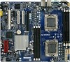
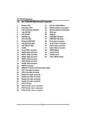
... 24-pin Power connector 10. SATA0 cable connector 43. Jumper block 15. SATA 4cable connector 18. System fan cable connector 26. GA-7TCSV-RH Motherboard Component 1. USB/GbE LAN ports 7. Winbond W83793G 38. Clear CMOS jumper 16. SGPIO connector 20. Primary CPU 31. Front panel... fan cable connector 25. Jumper block 14. System fan cable connector 24. PCI-E x8 slot (Gen2 at x1 bandwidth) 7 English GA-7TCSV-RH Motherboard 1.3. USB/GbE LAN ports 8. COM2 41. 8-pin Power connector 12. ITE IT8720F 35. VGA Memory 36. SATA3 cable connector 17...
... 24-pin Power connector 10. SATA0 cable connector 43. Jumper block 15. SATA 4cable connector 18. System fan cable connector 26. GA-7TCSV-RH Motherboard Component 1. USB/GbE LAN ports 7. Winbond W83793G 38. Clear CMOS jumper 16. SGPIO connector 20. Primary CPU 31. Front panel... fan cable connector 25. Jumper block 14. System fan cable connector 24. PCI-E x8 slot (Gen2 at x1 bandwidth) 7 English GA-7TCSV-RH Motherboard 1.3. USB/GbE LAN ports 8. COM2 41. 8-pin Power connector 12. ITE IT8720F 35. VGA Memory 36. SATA3 cable connector 17...

Manual
Page 9
... lever on the processor before placing cooling fan. 4. Please change the insert orientation. 2.1.1. Step 5 Once the CPU is supported by the motherboard. 5. The CPU only fits in permanent irreparable damage. 2. Step 4 Insert the CPU with the correct orientation. Step 2 Remove the plastic...well, it will overheat without the heatsink and/or fan, resulting in one orientation. Step 3 Lift the metal cover. English GA-7TCSV-RH Motherboard Chapter 2 Hardware Installation Process 2.1. The processor will cause improper installation. Please make sure the CPU type is properly placed, please...
... lever on the processor before placing cooling fan. 4. Please change the insert orientation. 2.1.1. Step 5 Once the CPU is supported by the motherboard. 5. The CPU only fits in permanent irreparable damage. 2. Step 4 Insert the CPU with the correct orientation. Step 2 Remove the plastic...well, it will overheat without the heatsink and/or fan, resulting in one orientation. Step 3 Lift the metal cover. English GA-7TCSV-RH Motherboard Chapter 2 Hardware Installation Process 2.1. The processor will cause improper installation. Please make sure the CPU type is properly placed, please...

Manual
Page 11
...please switch the direction. Before installing or removing memory modules, please make sure that they can be inserted only in only one direction. The motherboard supports DDR3 memory modules, whereby BIOS will automatically detect memory capacity and specifications. A memory module can be installed in one direction. The memory ... and brand. 2. Memory sockets for Processor 2 Memory sockets for Processor 1 11 Please make sure that the computer power is supported by the motherboard. English GA-7TCSV-RH Motherboard 2.2. Memory modules have a foolproof insertion design.
...please switch the direction. Before installing or removing memory modules, please make sure that they can be inserted only in only one direction. The motherboard supports DDR3 memory modules, whereby BIOS will automatically detect memory capacity and specifications. A memory module can be installed in one direction. The memory ... and brand. 2. Memory sockets for Processor 2 Memory sockets for Processor 1 11 Please make sure that the computer power is supported by the motherboard. English GA-7TCSV-RH Motherboard 2.2. Memory modules have a foolproof insertion design.

Manual
Page 13
English GA-7TCSV-RH Motherboard 2.3. Connect ribbon cables, cabinet wires, and power supply 2.3.1. I/O Back Panel Introduction 13
English GA-7TCSV-RH Motherboard 2.3. Connect ribbon cables, cabinet wires, and power supply 2.3.1. I/O Back Panel Introduction 13

Manual
Page 15
English GA-7TCSV-RH Motherboard LAN LED Description LED2 (Green/Yellow) LED1 (Green) Name LED1 LED2 Color Green Green Green Green Green Yellow Yellow Condition ON BLINK OFF OFF BLINK ON BLINK ON BLINK Description LAN Link / no Access LAN Access Idle 10Mbps connection Port identification with 10 Mbps connection 100Mbps connection Port identification with 100Mbps connection 1Gbps connection Port identification with 1Gbps connection 15
English GA-7TCSV-RH Motherboard LAN LED Description LED2 (Green/Yellow) LED1 (Green) Name LED1 LED2 Color Green Green Green Green Green Yellow Yellow Condition ON BLINK OFF OFF BLINK ON BLINK ON BLINK Description LAN Link / no Access LAN Access Idle 10Mbps connection Port identification with 10 Mbps connection 100Mbps connection Port identification with 100Mbps connection 1Gbps connection Port identification with 1Gbps connection 15

Manual
Page 16
SATA2 (SATA data cable connector) 10. CPU_FAN2 (CPU2 fan cable connector) 16. F_PANEL1 21. English GA-7TCSV-RH Motherboard 2.4. SSI_2X4P2 4. PSMI1 7. SATA1 (SATA data cable connector) 9. SATA5 (SATA data cable connector) 13. SATA3 (SATA data cable connector) 11. SYS_FAN3 (System fan connector) 19. JP1 ...
SATA2 (SATA data cable connector) 10. CPU_FAN2 (CPU2 fan cable connector) 16. F_PANEL1 21. English GA-7TCSV-RH Motherboard 2.4. SSI_2X4P2 4. PSMI1 7. SATA1 (SATA data cable connector) 9. SATA5 (SATA data cable connector) 13. SATA3 (SATA data cable connector) 11. SYS_FAN3 (System fan connector) 19. JP1 ...

Manual
Page 17
... use a power supply that is recommended that a power supply that can lead to an unstable system or a system that all the components on the motherboard. Please use a power supply that provides a 24-pin ATX power connector, please remove the small cover on the power connector on the... motherboard and connect tightly. otherwise, please do not remove it. 51 84 Pin No. 1 2 3 4 5 6 7 8 Definition GND GND GND GND P12V_CPU1 P12V_CPU1 P12V_CPU0 P12V_CPU0 13 1 12 ...
... use a power supply that is recommended that a power supply that can lead to an unstable system or a system that all the components on the motherboard. Please use a power supply that provides a 24-pin ATX power connector, please remove the small cover on the power connector on the... motherboard and connect tightly. otherwise, please do not remove it. 51 84 Pin No. 1 2 3 4 5 6 7 8 Definition GND GND GND GND P12V_CPU1 P12V_CPU1 P12V_CPU0 P12V_CPU0 13 1 12 ...

Manual
Page 18
For optional front USB cable, please contact your local dealer. 12 9 10 Pin No. 1 2 3 4 5 6 7 8 9 10 Definition 5V power 5V power -FUSB4 -FUSB5 +FUSB4 +FUSB5 GND GND NC NC 18 English GA-7TCSV-RH Motherboard 4 ) COM2 21 10 9 Pin No. 1 2 3 4 5 6 7 8 9 10 Definition DCDSIN2 SOUT2 DTR2GND DSR2RTS2CTS2RI2NC 5 ) F_USB1 (USB cable connector) Be careful with the polarity of the front USB connector. Check the pin assignment carefully while you connect the front USB cable, incorrect connection between the cable and connector will make the device unable to work or even damage it.
For optional front USB cable, please contact your local dealer. 12 9 10 Pin No. 1 2 3 4 5 6 7 8 9 10 Definition 5V power 5V power -FUSB4 -FUSB5 +FUSB4 +FUSB5 GND GND NC NC 18 English GA-7TCSV-RH Motherboard 4 ) COM2 21 10 9 Pin No. 1 2 3 4 5 6 7 8 9 10 Definition DCDSIN2 SOUT2 DTR2GND DSR2RTS2CTS2RI2NC 5 ) F_USB1 (USB cable connector) Be careful with the polarity of the front USB connector. Check the pin assignment carefully while you connect the front USB cable, incorrect connection between the cable and connector will make the device unable to work or even damage it.

Manual
Page 20
English GA-7TCSV-RH Motherboard 13 ) SGPIO2 SGPIO is stands for Serial General Purpose Input/Output which is the ground wire (GND). Most coolers are driven by the HBA and 1 ...
English GA-7TCSV-RH Motherboard 13 ) SGPIO2 SGPIO is stands for Serial General Purpose Input/Output which is the ground wire (GND). Most coolers are driven by the HBA and 1 ...
Manual
Page 21
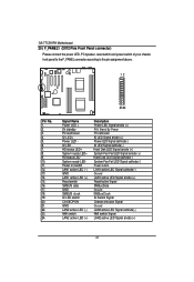
English GA-7TCSV-RH Motherboard 20 ) F_PANEL1 (2X12 Pins Front Panel connector) Please connect the power LED, PC speaker, reset switch and power switch of your chassis front panel to ...
English GA-7TCSV-RH Motherboard 20 ) F_PANEL1 (2X12 Pins Front Panel connector) Please connect the power LED, PC speaker, reset switch and power switch of your chassis front panel to ...

Manual
Page 23
GA-7TCSV-RH Motherboard 23 ) JP_REC1 ( BIOS Recovery jumper) English 1 1-2 close: Normal operation. (Default setting) 1 2-3 close: Enable BIOS Recovery function. 24 ) PASS_DIS1 (Skip Supervisor password jumper) 1 1-2 Close: Normal operation. (Default setting) 1 2-3 Close: Clear Supervisor Password in BIOS setup menu. 23
GA-7TCSV-RH Motherboard 23 ) JP_REC1 ( BIOS Recovery jumper) English 1 1-2 close: Normal operation. (Default setting) 1 2-3 close: Enable BIOS Recovery function. 24 ) PASS_DIS1 (Skip Supervisor password jumper) 1 1-2 Close: Normal operation. (Default setting) 1 2-3 Close: Clear Supervisor Password in BIOS setup menu. 23

Manual
Page 25
... in the right hand Main Menu - Quit and not save changes into CMOS Status Page Setup Menu and Option Page Setup Menu - GA-7TCSV-RH Motherboard Chapter 3 BIOS Setup BIOS (Basic Input and Output System) includes a CMOS SETUP utility which allows user to configure required settings or ...Reserved Reserved Reserved Load the Optimized Defaults Save all the CMOS changes, only for Main Menu 25 When the power is turned on the motherboard supplies the necessary power to the CMOS SRAM. ENTERINGSETUP When the power is turned off, the battery on , press the button during...
... in the right hand Main Menu - Quit and not save changes into CMOS Status Page Setup Menu and Option Page Setup Menu - GA-7TCSV-RH Motherboard Chapter 3 BIOS Setup BIOS (Basic Input and Output System) includes a CMOS SETUP utility which allows user to configure required settings or ...Reserved Reserved Reserved Load the Optimized Defaults Save all the CMOS changes, only for Main Menu 25 When the power is turned on the motherboard supplies the necessary power to the CMOS SRAM. ENTERINGSETUP When the power is turned off, the battery on , press the button during...

Manual
Page 27
Note that the "Day" automatically changed after you enter Phoenix BIOS Setup Utility, the Main Menu (Figure 1) will appear on the 24-hour military time clock. Use arrow keys to select among the items and press to accept or enter the sub-menu. Set the System Time (HH:MM:SS) System Time Set the System Date. GA-7TCSV-RH Motherboard Main Once you set the date. (Weekend: DD: MM: YY) (YY: 1099~2099) 27 Figure 1: Main System Time The time is calculated based on the screen.
Note that the "Day" automatically changed after you enter Phoenix BIOS Setup Utility, the Main Menu (Figure 1) will appear on the 24-hour military time clock. Use arrow keys to select among the items and press to accept or enter the sub-menu. Set the System Time (HH:MM:SS) System Time Set the System Date. GA-7TCSV-RH Motherboard Main Once you set the date. (Weekend: DD: MM: YY) (YY: 1099~2099) 27 Figure 1: Main System Time The time is calculated based on the screen.

Manual
Page 29
GA-7TCSV-RH Motherboard Advanced Processor Options Figure 1-1: Advanced Processor Options Advanced Processor Option This category includes the information of CPU. 29 Please note that setup menu options will be variable depends on the type of CPU Speed, Processor ID and Processor L2 / L3 Cache. And setup menu for Nehalem CPU Power Management, Simultanceous Multi Threading, Intel Virtualizational Technology, Machine Checking, Fast String operations, Execute Disable Bit, Set Max Ext CPUID =3, Echo TPR, and Discrete MTRR Allocation.
GA-7TCSV-RH Motherboard Advanced Processor Options Figure 1-1: Advanced Processor Options Advanced Processor Option This category includes the information of CPU. 29 Please note that setup menu options will be variable depends on the type of CPU Speed, Processor ID and Processor L2 / L3 Cache. And setup menu for Nehalem CPU Power Management, Simultanceous Multi Threading, Intel Virtualizational Technology, Machine Checking, Fast String operations, Execute Disable Bit, Set Max Ext CPUID =3, Echo TPR, and Discrete MTRR Allocation.

Manual
Page 31
... Desired state for the Nehalem core C3 state include in the CST as ACPI C2 state. (Default setting) Disabled Disable OS ACPI C2 Report. GA-7TCSV-RH Motherboard transition on any of those Logical Processors . Turbo Mode can be engaged with dependencies and may initiate the transition on all of those Logical...
... Desired state for the Nehalem core C3 state include in the CST as ACPI C2 state. (Default setting) Disabled Disable OS ACPI C2 Report. GA-7TCSV-RH Motherboard transition on any of those Logical Processors . Turbo Mode can be engaged with dependencies and may initiate the transition on all of those Logical...


