Manual
Page 1
GA-73UM-S2H LGA775 socket motherboard for Intel® CoreTM processor family/ Intel® Pentium® processor family/Intel® Celeron® processor family User's Manual Rev. 1001 12ME-73UMS2H-1001R
GA-73UM-S2H LGA775 socket motherboard for Intel® CoreTM processor family/ Intel® Pentium® processor family/Intel® Celeron® processor family User's Manual Rev. 1001 12ME-73UMS2H-1001R

Manual
Page 2
Motherboard GA-73UM-S2H Oct. 5, 2007 Motherboard GA-73UM-S2H Oct. 5, 2007
Motherboard GA-73UM-S2H Oct. 5, 2007 Motherboard GA-73UM-S2H Oct. 5, 2007

Manual
Page 3
... 1.0. Example: The trademarks mentioned in any means without prior notice. Changes to GIGABYTE UNITED INC. No part of GIGABYTE. GIGABYTE UNITED INC. Check your motherboard looks like this manual are legally registered to use of this product, GIGABYTE provides the following types of GIGABYTE branded motherboards. The logo is designated by GIGA-BYTE TECHNOLOGY CO., LTD. Copyright...
... 1.0. Example: The trademarks mentioned in any means without prior notice. Changes to GIGABYTE UNITED INC. No part of GIGABYTE. GIGABYTE UNITED INC. Check your motherboard looks like this manual are legally registered to use of this product, GIGABYTE provides the following types of GIGABYTE branded motherboards. The logo is designated by GIGA-BYTE TECHNOLOGY CO., LTD. Copyright...

Manual
Page 4
Table of Contents Box Contents ...6 OptionalItems ...6 GA-73UM-S2H Motherboard Layout 7 Block Diagram ...8 Chapter 1 Hardware Installation 9 1-1 Installation Precautions 9 1-2 Product Specifications 10 1-3 Installing the CPU and CPU Cooler 13 1-3-1 Installing the CPU 13 1-3-2 Installing the CPU ...
Table of Contents Box Contents ...6 OptionalItems ...6 GA-73UM-S2H Motherboard Layout 7 Block Diagram ...8 Chapter 1 Hardware Installation 9 1-1 Installation Precautions 9 1-2 Product Specifications 10 1-3 Installing the CPU and CPU Cooler 13 1-3-1 Installing the CPU 13 1-3-2 Installing the CPU ...

Manual
Page 6
Box Contents GA-73UM-S2H motherboard Motherboard driver disk Motherboard driver disk (for Windows Vista) User's Manual Intel® LGA775 CPU Installation Guide One IDE cable and one floppy disk drive cable Two SATA 3Gb/s cables I/O Shield • The box contents above are subject to change without notice. • The motherboard image is for reference only and the...
Box Contents GA-73UM-S2H motherboard Motherboard driver disk Motherboard driver disk (for Windows Vista) User's Manual Intel® LGA775 CPU Installation Guide One IDE cable and one floppy disk drive cable Two SATA 3Gb/s cables I/O Shield • The box contents above are subject to change without notice. • The motherboard image is for reference only and the...

Manual
Page 7
GA-73UM-S2H Motherboard Layout KB_MS ATX_12V VGA DVI HDMI OPTICAL USB ESATA 1394 LAN USB RTL 8211B AUDIO F_AUDIO CD_IN PCIE_1 PCIE_16 CODEC PCI1 PCI2 SPDIF_IO F_USB3 F_USB1 F_USB2 LGA775 CPU_FAN ATX LPT GA-73UM-S2H nVIDIA® GeForce 7150/ nForce 630i IDE SATAII1 SATAII0 SATAII2 DDRII1 DDRII2 BIOS TSB43AB23 IT8718 CLR_CMOS CI BATTERY F1_1394 FDD SYS_FAN COMA PWR_LED F_PANEL - 7 -
GA-73UM-S2H Motherboard Layout KB_MS ATX_12V VGA DVI HDMI OPTICAL USB ESATA 1394 LAN USB RTL 8211B AUDIO F_AUDIO CD_IN PCIE_1 PCIE_16 CODEC PCI1 PCI2 SPDIF_IO F_USB3 F_USB1 F_USB2 LGA775 CPU_FAN ATX LPT GA-73UM-S2H nVIDIA® GeForce 7150/ nForce 630i IDE SATAII1 SATAII0 SATAII2 DDRII1 DDRII2 BIOS TSB43AB23 IT8718 CLR_CMOS CI BATTERY F1_1394 FDD SYS_FAN COMA PWR_LED F_PANEL - 7 -

Manual
Page 9
...Always remove the AC power by your hands dry and first touch a metal object to eliminate static electricity. • Prior to installing the motherboard, please have it on top of an antistatic pad or within the computer casing. • Do not place the computer system on an uneven... components. • When connecting hardware components to the internal connectors on the computer power during the installation process can become damaged as a motherboard, CPU or memory. Hardware Installation These stickers are uncertain about any metal leads or connectors. • It is best to the use ...
...Always remove the AC power by your hands dry and first touch a metal object to eliminate static electricity. • Prior to installing the motherboard, please have it on top of an antistatic pad or within the computer casing. • Do not place the computer system on an uneven... components. • When connecting hardware components to the internal connectors on the computer power during the installation process can become damaged as a motherboard, CPU or memory. Hardware Installation These stickers are uncertain about any metal leads or connectors. • It is best to the use ...

Manual
Page 10
...chip Š Up to 2 IEEE 1394a ports (1 on the back panel, 1 via the USB brackets connected to the internal USB headers) GA-73UM-S2H Motherboard - 10 - 1-2 Product Specifications CPU Front Side Bus Chipset Memory Onboard Graphics Audio LAN Expansion Slots Storage Interface IEEE 1394a USB Š ...174; Pentium® 4 processor Extreme Edition/Intel® Pentium® 4 processor/ Intel® Celeron® processor in the LGA 775 package (Go to GIGABYTE's website for the latest CPU support list.) Š L2 cache varies with CPU Š 1333/1066/800 MHz FSB Š nVIDIA® GeForce 7150/...
...chip Š Up to 2 IEEE 1394a ports (1 on the back panel, 1 via the USB brackets connected to the internal USB headers) GA-73UM-S2H Motherboard - 10 - 1-2 Product Specifications CPU Front Side Bus Chipset Memory Onboard Graphics Audio LAN Expansion Slots Storage Interface IEEE 1394a USB Š ...174; Pentium® 4 processor Extreme Edition/Intel® Pentium® 4 processor/ Intel® Celeron® processor in the LGA 775 package (Go to GIGABYTE's website for the latest CPU support list.) Š L2 cache varies with CPU Š 1333/1066/800 MHz FSB Š nVIDIA® GeForce 7150/...

Manual
Page 12
GA-73UM-S2H Motherboard - 12 - Unique Features Bundled Software Operating System Form Factor Š Support for @BIOS Š Support for Download Center Š Support for Q-Flash Š Support for ... Form Factor; 24.4cm x 22.0cm (Note 1) The DVI-D port does not support D-Sub connection by adapter. (Note 2) Available functions in Easytune may differ by motherboard model.
GA-73UM-S2H Motherboard - 12 - Unique Features Bundled Software Operating System Form Factor Š Support for @BIOS Š Support for Download Center Š Support for Q-Flash Š Support for ... Form Factor; 24.4cm x 22.0cm (Note 1) The DVI-D port does not support D-Sub connection by adapter. (Note 2) Available functions in Easytune may differ by motherboard model.

Manual
Page 13
... A. It is not installed, otherwise overheating and damage of the CPU. Locate the alignment keys on the motherboard CPU socket and the notches on the CPU - 13 - mended that the motherboard supports the CPU. (Go to GIGABYTE's website for the peripherals. If you may occur. • Set the CPU host frequency in accordance...
... A. It is not installed, otherwise overheating and damage of the CPU. Locate the alignment keys on the motherboard CPU socket and the notches on the CPU - 13 - mended that the motherboard supports the CPU. (Go to GIGABYTE's website for the peripherals. If you may occur. • Set the CPU host frequency in accordance...

Manual
Page 14
... socket. CPU Socket Lever Step 1: Completely raise the CPU socket lever. Step 3: Lift the metal load plate on the CPU socket. GA-73UM-S2H Motherboard - 14 - Align the CPU pin one marking (triangle) with the pin one corner of the CPU socket (or you may align the CPU notches with ...
... socket. CPU Socket Lever Step 1: Completely raise the CPU socket lever. Step 3: Lift the metal load plate on the CPU socket. GA-73UM-S2H Motherboard - 14 - Align the CPU pin one marking (triangle) with the pin one corner of the CPU socket (or you may align the CPU notches with ...

Manual
Page 15
... and Female push pins are joined closely. (Refer to your CPU cooler installation manual for instructions on the motherboard. Step 4: You should hear a "click" when pushing down on the motherboard. Use extreme care when removing the CPU cooler because the thermal grease/tape between the CPU cooler and CPU... push pin is inserted as the example cooler.) Step 1: Apply an even and thin layer of thermal grease on the surface of the motherboard. Hardware Installation Direction of the Arrow Sign on the Male Push Pin Male Push Pin The Top of Female Push Pin Female Push Pin Step...
... and Female push pins are joined closely. (Refer to your CPU cooler installation manual for instructions on the motherboard. Step 4: You should hear a "click" when pushing down on the motherboard. Use extreme care when removing the CPU cooler because the thermal grease/tape between the CPU cooler and CPU... push pin is inserted as the example cooler.) Step 1: Apply an even and thin layer of thermal grease on the surface of the motherboard. Hardware Installation Direction of the Arrow Sign on the Male Push Pin Male Push Pin The Top of Female Push Pin Female Push Pin Step...

Manual
Page 16
... in one direction. Place the memory module on the memory and insert it can be used. (Go to GIGABYTE's website for the latest memory support list.) • Always turn off the computer and unplug the power cord... from the power outlet to prevent damage to install DDR2 DIMMs on this motherboard. As indicated in only one direction. If you begin to install the memory: • Make sure that ...notch, so it vertically into place when the memory module is recommended that the motherboard supports the memory. GA-73UM-S2H Motherboard - 16 -
... in one direction. Place the memory module on the memory and insert it can be used. (Go to GIGABYTE's website for the latest memory support list.) • Always turn off the computer and unplug the power cord... from the power outlet to prevent damage to install DDR2 DIMMs on this motherboard. As indicated in only one direction. If you begin to install the memory: • Make sure that ...notch, so it vertically into place when the memory module is recommended that the motherboard supports the memory. GA-73UM-S2H Motherboard - 16 -
Manual
Page 17
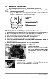
1-5 Installing an Expansion Card Read the following guidelines before installing an expansion card to install an expansion card: • Make sure the motherboard supports the expansion card. Locate an expansion slot that came with the slot, and press down on your computer. Make sure the metal contacts on ...
1-5 Installing an Expansion Card Read the following guidelines before installing an expansion card to install an expansion card: • Make sure the motherboard supports the expansion card. Locate an expansion slot that came with the slot, and press down on your computer. Make sure the metal contacts on ...

Manual
Page 18
... The DVI-D port supports DVI-D specifictation. HDMI Port The HDMI (High-Definition Multimedia Interface) provides an all-digital audio/video interface to connect a PS/2 keyboard. GA-73UM-S2H Motherboard - 18 - Connect the HDMI audio/ video device to NVIDIA HDMI Audio Wave.
... The DVI-D port supports DVI-D specifictation. HDMI Port The HDMI (High-Definition Multimedia Interface) provides an all-digital audio/video interface to connect a PS/2 keyboard. GA-73UM-S2H Motherboard - 18 - Connect the HDMI audio/ video device to NVIDIA HDMI Audio Wave.

Manual
Page 19
... jack. Optical S/PDIF Out Connector This connector provides digital audio out to an external audio system that your device and then remove it from the motherboard. • When removing the cable, pull it side to side to prevent an electrical short inside the cable connector. - 19 - The following describes the states...
... jack. Optical S/PDIF Out Connector This connector provides digital audio out to an external audio system that your device and then remove it from the motherboard. • When removing the cable, pull it side to side to prevent an electrical short inside the cable connector. - 19 - The following describes the states...

Manual
Page 20
... Non-protected contents HD-DVD Blu-ray Suitable Resolution Windows XP Windows Vista 1920 x 1080p 1920 x 1080p 1920 x 1080p 1920 x 1080p 1920 x 1080p 1920 x 1080p GA-73UM-S2H Motherboard - 20 - Mic In Jack (Pink) The default Mic in Chapter 5, "Configuring 2/4/5.1/7.1-Channel Audio." A. Dual Combination Supported or Not Display DVI-D + D-Sub Yes DVI-D + HDMI No...
... Non-protected contents HD-DVD Blu-ray Suitable Resolution Windows XP Windows Vista 1920 x 1080p 1920 x 1080p 1920 x 1080p 1920 x 1080p 1920 x 1080p 1920 x 1080p GA-73UM-S2H Motherboard - 20 - Mic In Jack (Pink) The default Mic in Chapter 5, "Configuring 2/4/5.1/7.1-Channel Audio." A. Dual Combination Supported or Not Display DVI-D + D-Sub Yes DVI-D + HDMI No...

Manual
Page 21
... devices and your devices are compliant with the connectors you wish to connect. • Before installing the devices, be sure to the connector on the motherboard. - 21 - Hardware Installation 1-7 Internal Connectors 1 3 17 2 6 11 7 12 19 9 13 18 14 5 15 8 16 10 4 1) ATX_12V 2) ATX 3) CPU_FAN 4) SYS_FAN 5) FDD 6) IDE 7) SATAII0/1/2 8) PWR_LED 9) BATTERY 10...
... devices and your devices are compliant with the connectors you wish to connect. • Before installing the devices, be sure to the connector on the motherboard. - 21 - Hardware Installation 1-7 Internal Connectors 1 3 17 2 6 11 7 12 19 9 13 18 14 5 15 8 16 10 4 1) ATX_12V 2) ATX 3) CPU_FAN 4) SYS_FAN 5) FDD 6) IDE 7) SATAII0/1/2 8) PWR_LED 9) BATTERY 10...

Manual
Page 22
... power connector is not connected, the computer will not start. • To meet expansion requirements, it is turned off and all the components on the motherboard. When using a 2x10 power supply. 1 3 2 4 ATX_12V ATX_12V: Pin No. 1 2 3 4 Definition GND GND +12V +12V 12 24 1 13 ATX ATX: Pin No. 1 2 3 4 5 6 7 ... PS_ON(soft On/Off) GND GND GND -5V +5V +5V +5V (Only for 2x12-pin ATX) GND (Only for 2x12-pin ATX) GA-73UM-S2H Motherboard - 22 - Connect the power supply cable to the CPU. Do not insert the power supply cable into pins under the protective cover when using ...
... power connector is not connected, the computer will not start. • To meet expansion requirements, it is turned off and all the components on the motherboard. When using a 2x10 power supply. 1 3 2 4 ATX_12V ATX_12V: Pin No. 1 2 3 4 Definition GND GND +12V +12V 12 24 1 13 ATX ATX: Pin No. 1 2 3 4 5 6 7 ... PS_ON(soft On/Off) GND GND GND -5V +5V +5V +5V (Only for 2x12-pin ATX) GND (Only for 2x12-pin ATX) GA-73UM-S2H Motherboard - 22 - Connect the power supply cable to the CPU. Do not insert the power supply cable into pins under the protective cover when using ...
Manual
Page 23
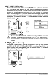
... connect fan cables to the fan headers to connect it is used to connect a floppy disk drive. Hardware Installation 3/4) CPU_FAN/SYS_FAN (Fan Headers) The motherboard has a 4-pin CPU fan header (CPU_FAN) and a 4-pin system fan header (SYS_FAN). When connecting a fan cable, be sure to prevent your... KB, 720 KB, 1.2 MB, 1.44 MB, and 2.88 MB. Overheating may hang. • These fan headers are not configuration jumper blocks. The motherboard supports CPU fan speed control, which requires the use of different color. 33 1 34 2 - 23 - For optimum heat dissipation, it in damage to ...
... connect fan cables to the fan headers to connect it is used to connect a floppy disk drive. Hardware Installation 3/4) CPU_FAN/SYS_FAN (Fan Headers) The motherboard has a 4-pin CPU fan header (CPU_FAN) and a 4-pin system fan header (SYS_FAN). When connecting a fan cable, be sure to prevent your... KB, 720 KB, 1.2 MB, 1.44 MB, and 2.88 MB. Overheating may hang. • These fan headers are not configuration jumper blocks. The motherboard supports CPU fan speed control, which requires the use of different color. 33 1 34 2 - 23 - For optimum heat dissipation, it in damage to ...


