
Manual
Page 1
GA-6TXSL-RH Intel® Core i7 Series Processor Motherboard USER'S MANUAL Intel® CoreTM2 Quad processorMotherboard Rev. 1001 * The WEEE marking on the product indicates this product must not be disposed of with user's other household waste and must be handed over to a designated collection point for the recycling of waste electrical and electronic equipment!! * The WEEE marking applies only in European Union's member states.
GA-6TXSL-RH Intel® Core i7 Series Processor Motherboard USER'S MANUAL Intel® CoreTM2 Quad processorMotherboard Rev. 1001 * The WEEE marking on the product indicates this product must not be disposed of with user's other household waste and must be handed over to a designated collection point for the recycling of waste electrical and electronic equipment!! * The WEEE marking applies only in European Union's member states.

Manual
Page 2
... Manual". For detailed information related to Gigabyte's unique features, please go to "Technology Guide" section on Gigabyte's website to assist in the use of this manual may be reproduced, copied, translated, or transmitted in the manual are subject to their respective companies. English GA-6TXSL-RH Motherboard Copyright © 2009 GIGA-BYTE TECHNOLOGY CO...
... Manual". For detailed information related to Gigabyte's unique features, please go to "Technology Guide" section on Gigabyte's website to assist in the use of this manual may be reproduced, copied, translated, or transmitted in the manual are subject to their respective companies. English GA-6TXSL-RH Motherboard Copyright © 2009 GIGA-BYTE TECHNOLOGY CO...

Manual
Page 3
English Table of Contents Table of Content Item Checklist...4 Chapter 1 Introduction...5 1-1 Features Summary 5 1.2 GA-6TXSL-RH Motherboard Components 7 Chapter 2 Hardware Installation Process 9 2-1: Install Memory Modules 9 2-2: Connect ribbon cables, cabinet wires, and power supply 11 2-3: Connectors Introduction & Jumper Setting 12 2-4: Block Diagram ...
English Table of Contents Table of Content Item Checklist...4 Chapter 1 Introduction...5 1-1 Features Summary 5 1.2 GA-6TXSL-RH Motherboard Components 7 Chapter 2 Hardware Installation Process 9 2-1: Install Memory Modules 9 2-2: Connect ribbon cables, cabinet wires, and power supply 11 2-3: Connectors Introduction & Jumper Setting 12 2-4: Block Diagram ...

Manual
Page 4
... electricity, you should follow some precautions whenever you can still attach the spacers to the chassis... English GA-6TXSL-RH Motherboard Item Checklist The GA-6TXSL-RH motherboard Floppy cable CD for motherboard driver & utility GA-6TXSL-RH Quick Reference Guide Serial ATA cable x 6 I/O Shield Kit SATA Power cable x 6 USB+1394...
... electricity, you should follow some precautions whenever you can still attach the spacers to the chassis... English GA-6TXSL-RH Motherboard Item Checklist The GA-6TXSL-RH motherboard Floppy cable CD for motherboard driver & utility GA-6TXSL-RH Quick Reference Guide Serial ATA cable x 6 I/O Shield Kit SATA Power cable x 6 USB+1394...

Manual
Page 6
English GA-6TXSL-RH Motherboard On-Board LAN On-Board Peripherals Hardware Monitor BIOS Additional Features Intel® 82567LM GbE controller Supports WOL, PXE 1 x Floppy connector &#...
English GA-6TXSL-RH Motherboard On-Board LAN On-Board Peripherals Hardware Monitor BIOS Additional Features Intel® 82567LM GbE controller Supports WOL, PXE 1 x Floppy connector &#...
Manual
Page 7
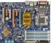
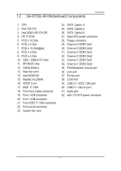
.... Front Auio Cable connector 19. Channel 2 DDR3 Slot2 33. USB2.0 + IEEE 1394 port 40. Printer port 38. Audio port 42. 4pin 12V ATX power connector 7 1.2 GA-6TXSL-RH Motherboard Components Introduction 1. IEEE TI 1394 18. SPI BIOS Chip 12. Front panel connector 23. Channel 3 DDR3 Slot1 30. Channel 1 DDR3 Slot2 35. SATA Cable2...
.... Front Auio Cable connector 19. Channel 2 DDR3 Slot2 33. USB2.0 + IEEE 1394 port 40. Printer port 38. Audio port 42. 4pin 12V ATX power connector 7 1.2 GA-6TXSL-RH Motherboard Components Introduction 1. IEEE TI 1394 18. SPI BIOS Chip 12. Front panel connector 23. Channel 3 DDR3 Slot1 30. Channel 1 DDR3 Slot2 35. SATA Cable2...
Manual
Page 8
English GA-6TXSL-RH Motherboard 28 1 37 35 36 27 29 30 31 32 33 34 46 2 24 25 26 23 22 3 4 21 11 20 12 19 5 6 7 8 9 10 42 13 16 18 39 40 41 14 15 17 38 8
English GA-6TXSL-RH Motherboard 28 1 37 35 36 27 29 30 31 32 33 34 46 2 24 25 26 23 22 3 4 21 11 20 12 19 5 6 7 8 9 10 42 13 16 18 39 40 41 14 15 17 38 8
Manual
Page 9
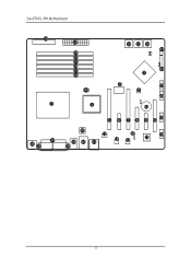
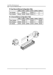
For detail DIMM installation, please refer to the following instructions. Channel 3 Channel 2 Channel 1 9 The BIOS will automatically detects memory type and size during system boot. It supports Triple Channels Technology. 2-1: Install Memory Modules Hardware Installation Process GA-6TXSL-RH has 6 triple inline memory module (DIMM) sokcets.
For detail DIMM installation, please refer to the following instructions. Channel 3 Channel 2 Channel 1 9 The BIOS will automatically detects memory type and size during system boot. It supports Triple Channels Technology. 2-1: Install Memory Modules Hardware Installation Process GA-6TXSL-RH has 6 triple inline memory module (DIMM) sokcets.
Manual
Page 10
Four M odules DS/SS DS/SS DS/SS DS/SS - - - - 3 Channel Memory Configurations Table Three Modules Four M odules Six Modules DDR3_2 - DS/SS - - - - Supported DIMM Module Type Dual Channel Memory Configurations Table DDR3_2 DDR3_1 DDR3_4 DDR3_3 DDR3_6 DDR3_5 Two M odules - - DS/SS DDR3_3 DS/SS DS/SS DS/SS DDR3_6 - - DS/SS DDR3_5 DS/SS DS/SS DS/SS 10 DS/SS - - DS/SS DS/SS DDR3_1 DS/SS DS/SS DS/SS DDR3_4 - - English GA-6TXSL-RH Motherboard Table 1.
Four M odules DS/SS DS/SS DS/SS DS/SS - - - - 3 Channel Memory Configurations Table Three Modules Four M odules Six Modules DDR3_2 - DS/SS - - - - Supported DIMM Module Type Dual Channel Memory Configurations Table DDR3_2 DDR3_1 DDR3_4 DDR3_3 DDR3_6 DDR3_5 Two M odules - - DS/SS DDR3_3 DS/SS DS/SS DS/SS DDR3_6 - - DS/SS DDR3_5 DS/SS DS/SS DS/SS 10 DS/SS - - DS/SS DS/SS DDR3_1 DS/SS DS/SS DS/SS DDR3_4 - - English GA-6TXSL-RH Motherboard Table 1.
Manual
Page 12
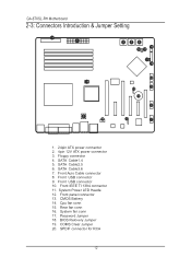
... Jumper 19. System Power LED Heade 12. SATA Cable1.4 5. CMOS Battery 14. Floppy connector 4. Front IEEE TI 1394 connector 11. COMS Clear Jumper 20. English GA-6TXSL-RH Motherboard 2-3: Connectors Introduction & Jumper Setting 3 1 456 16 18 17 11 19 14 2 15 10 9 12 13 8 20 7 1. 24pin ATX power connector 2. 4pin 12V ATX power...
... Jumper 19. System Power LED Heade 12. SATA Cable1.4 5. CMOS Battery 14. Floppy connector 4. Front IEEE TI 1394 connector 11. COMS Clear Jumper 20. English GA-6TXSL-RH Motherboard 2-3: Connectors Introduction & Jumper Setting 3 1 456 16 18 17 11 19 14 2 15 10 9 12 13 8 20 7 1. 24pin ATX power connector 2. 4pin 12V ATX power...

Manual
Page 14
English GA-6TXSL-RH Motherboard 3 ) FDD (Floppy Connector) ATX_12V Please connect the floppy drive ribbon cables to FDD. FDD 2 34 1 33 IDE 14 The red stripe of the ribbon cable must be the same side with the Pin1. It supports 720K,1.2M,1.44M and 2.88Mbytes floppy disk types.
English GA-6TXSL-RH Motherboard 3 ) FDD (Floppy Connector) ATX_12V Please connect the floppy drive ribbon cables to FDD. FDD 2 34 1 33 IDE 14 The red stripe of the ribbon cable must be the same side with the Pin1. It supports 720K,1.2M,1.44M and 2.88Mbytes floppy disk types.
Manual
Page 16
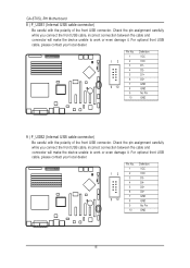
English GA-6TXSL-RH Motherboard 8 ) F_USB1 (Internal USB cable connector) Be careful with the polarity of the front USB connector. For optional front USB cable, please contact your local ...
English GA-6TXSL-RH Motherboard 8 ) F_USB1 (Internal USB cable connector) Be careful with the polarity of the front USB connector. For optional front USB cable, please contact your local ...

Manual
Page 18
... cathode(-) Pin removed Pin removed Pin removed Pin removed Pin removed Speaker anode(+) Pin removed ND Pin removed ND Pin removed Speaker cathode(-) 18 English GA-6TXSL-RH Motherboard 12 ) F_Panel (2X10 Pins Front Panel connector) Please connect the power LED, PC speaker, reset switch and power switch of your chassis front panel...
... cathode(-) Pin removed Pin removed Pin removed Pin removed Pin removed Speaker anode(+) Pin removed ND Pin removed ND Pin removed Speaker cathode(-) 18 English GA-6TXSL-RH Motherboard 12 ) F_Panel (2X10 Pins Front Panel connector) Please connect the power LED, PC speaker, reset switch and power switch of your chassis front panel...

Manual
Page 20
These connectors are for system use only. 1 Pin No. 1 2 3 4 Definition GND 12V Sense Control 20 Definition 1 1 GND 2 12V 3 Sense 4 Control 16 ) SYS_FAN (System Fan Connector) This connector allows you to link with the cooling fan on the system case to lower the system temperature. These connectors are for system use only. Pin No. English GA-6TXSL-RH Motherboard 15 ) REAR_FAN (Front Fan and Rear fan cable connectors) This connector allows you to link with the cooling fan on the system case to lower the system temperature.
These connectors are for system use only. 1 Pin No. 1 2 3 4 Definition GND 12V Sense Control 20 Definition 1 1 GND 2 12V 3 Sense 4 Control 16 ) SYS_FAN (System Fan Connector) This connector allows you to link with the cooling fan on the system case to lower the system temperature. These connectors are for system use only. Pin No. English GA-6TXSL-RH Motherboard 15 ) REAR_FAN (Front Fan and Rear fan cable connectors) This connector allows you to link with the cooling fan on the system case to lower the system temperature.

Manual
Page 22
... value doesn't include the "Shunter" to prevent from improper use this jumper. Definition 1 GND 1 2 Pin Removed 3 SPDIF-IN 4 SPDIF-OUT 5 GND 22 Pin No. English GA-6TXSL-RH Motherboard 19 ) JP1 (Clear CMOS jumper) You may clear the CMOS data to restore its default values by this jumper.
... value doesn't include the "Shunter" to prevent from improper use this jumper. Definition 1 GND 1 2 Pin Removed 3 SPDIF-IN 4 SPDIF-OUT 5 GND 22 Pin No. English GA-6TXSL-RH Motherboard 19 ) JP1 (Clear CMOS jumper) You may clear the CMOS data to restore its default values by this jumper.

Manual
Page 24
... the BIOS setup screen by pressing "Ctrl + F1". Quit and not save changes into CMOS Status Page Setup Menu and Option Page Setup Menu - English GA-6TXSL-RH Motherboard Chapter 3 BIOS Setup BIOS (Basic Input and Output System) includes a CMOS SETUP utility which allows user to configure required settings or to the CMOS...
... the BIOS setup screen by pressing "Ctrl + F1". Quit and not save changes into CMOS Status Page Setup Menu and Option Page Setup Menu - English GA-6TXSL-RH Motherboard Chapter 3 BIOS Setup BIOS (Basic Input and Output System) includes a CMOS SETUP utility which allows user to configure required settings or to the CMOS...
Manual
Page 26
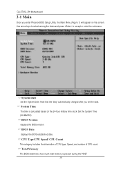
...:SS) BIOS Version displays the BIOS version. Use arrow keys to select among the items and press to accept or enter the sub-menu. English GA-6TXSL-RH Motherboard 3-1 Main Once you set the date. BIOS Date displays the BIOS established date.
...:SS) BIOS Version displays the BIOS version. Use arrow keys to select among the items and press to accept or enter the sub-menu. English GA-6TXSL-RH Motherboard 3-1 Main Once you set the date. BIOS Date displays the BIOS established date.
Manual
Page 28
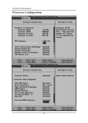
English GA-6TXSL-RH Motherboard Processor Configuration 28
English GA-6TXSL-RH Motherboard Processor Configuration 28
Manual
Page 30
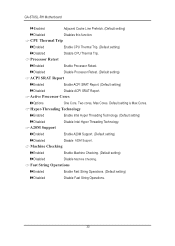
... Thermal Trip Enabled Enable CPU Thermal Trip. (Default setting) Disabled Disable CPU Thermal Trip. Active Processor Cores Options One Core, Two cores, Max Cores. English GA-6TXSL-RH Motherboard Enabled Adjacent Cache Line Prefetch. (Default setting) Disabled Disables this function. Disabled Disable Processor Retest. (Default setting) ACPI SRAT Report Enabled Enable ACPI SRAT...
... Thermal Trip Enabled Enable CPU Thermal Trip. (Default setting) Disabled Disable CPU Thermal Trip. Active Processor Cores Options One Core, Two cores, Max Cores. English GA-6TXSL-RH Motherboard Enabled Adjacent Cache Line Prefetch. (Default setting) Disabled Disables this function. Disabled Disable Processor Retest. (Default setting) ACPI SRAT Report Enabled Enable ACPI SRAT...

Manual
Page 32
English GA-6TXSL-RH Motherboard Memory Configuration 32
English GA-6TXSL-RH Motherboard Memory Configuration 32


