User Manual
Page 2
...may cause bodily harm or damage to provide users with in the user manual. website. (http://www.gigabyte.com.tw) The following are not detached from the casing prior to transportation of the computer system, resulting in a manner other components. Using the product incorrectly or...5. Any loss/damage caused by the warranty: 1. Unapproved modification of the "3D Mercury" series, please visit Gigabyte Tech. Be sure to follow the installation process with the most optimal solution for purchasing Gigabyte Tech. is dedicated to the integration of computer products may possibly burn out...
...may cause bodily harm or damage to provide users with in the user manual. website. (http://www.gigabyte.com.tw) The following are not detached from the casing prior to transportation of the computer system, resulting in a manner other components. Using the product incorrectly or...5. Any loss/damage caused by the warranty: 1. Unapproved modification of the "3D Mercury" series, please visit Gigabyte Tech. Be sure to follow the installation process with the most optimal solution for purchasing Gigabyte Tech. is dedicated to the integration of computer products may possibly burn out...
User Manual
Page 3
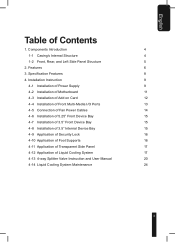
... 4-9 Application of Security Lock 16 4-10 Application of Foot Supports 16 4-11 Application of Transparent Side Panel 17 4-12 Application of Contents 1. Features 6 3. Components Introduction 4 1-1 Casing's Internal Structure 4 1-2 Front, Rear, and Left Side Panel Structure 5 2.
... 4-9 Application of Security Lock 16 4-10 Application of Foot Supports 16 4-11 Application of Transparent Side Panel 17 4-12 Application of Contents 1. Features 6 3. Components Introduction 4 1-1 Casing's Internal Structure 4 1-2 Front, Rear, and Left Side Panel Structure 5 2.
User Manual
Page 4
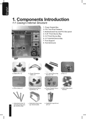
... power supply retainer plate. Tool Enclosure 5 2 3 6 8 7 a. Stand off x 12 b. Key x 2 e. Wire clamp x 2 f. AM2 Water block bracket i. j. Extended screw for securing power sup- 4 ply retainer plate. Gigabyte Liquid Coolant x 2 Components Introduction 1-1 Casing's Internal Structure 1. Foot Support 8. k. PCI Tool-Free Fastener 3. English 1.
... power supply retainer plate. Tool Enclosure 5 2 3 6 8 7 a. Stand off x 12 b. Key x 2 e. Wire clamp x 2 f. AM2 Water block bracket i. j. Extended screw for securing power sup- 4 ply retainer plate. Gigabyte Liquid Coolant x 2 Components Introduction 1-1 Casing's Internal Structure 1. Foot Support 8. k. PCI Tool-Free Fastener 3. English 1.
User Manual
Page 6
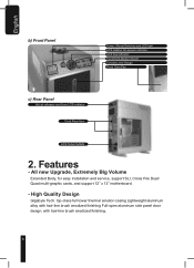
top-class full tower thermal solution casing Lightweight aluminum alloy with hair-line brush anodized finishing Full-open aluminum side panel door design, with hair-line brush anodized finishing. 6 All new Upgrade, ... Volume Extended Body, for easy installation and service, support SLI, Cross Fire Dual/ Quad multi-graphic cards, and support 12" x 13" motherboard. - High Quality Design Gigabyte Tech. Features - English b) Front Panel Power / Reset Switches and LED light LCS radiator fan speed controller LCS flow indicator Front Multi-Media I/O port Coolant Level...
top-class full tower thermal solution casing Lightweight aluminum alloy with hair-line brush anodized finishing Full-open aluminum side panel door design, with hair-line brush anodized finishing. 6 All new Upgrade, ... Volume Extended Body, for easy installation and service, support SLI, Cross Fire Dual/ Quad multi-graphic cards, and support 12" x 13" motherboard. - High Quality Design Gigabyte Tech. Features - English b) Front Panel Power / Reset Switches and LED light LCS radiator fan speed controller LCS flow indicator Front Multi-Media I/O port Coolant Level...
User Manual
Page 12
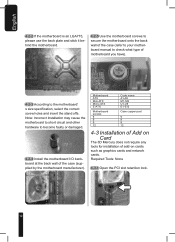
... onto the back wall of the case (refer to your motherboard manual to check what type of motherboard you have). 4-2-3 According to become faulty or damaged. 4-2-4 Install the motherboard I/O backboard at the back wall of add-on Card The 3D Mercury does not require any tools for... installation of the case (supplied by the motherboard manufacturer). Note: Incorrect installation may cause the motherboard to short circuit and other hardware to...
... onto the back wall of the case (refer to your motherboard manual to check what type of motherboard you have). 4-2-3 According to become faulty or damaged. 4-2-4 Install the motherboard I/O backboard at the back wall of add-on Card The 3D Mercury does not require any tools for... installation of the case (supplied by the motherboard manufacturer). Note: Incorrect installation may cause the motherboard to short circuit and other hardware to...
User Manual
Page 13
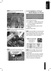
... causes faults will void your warranty The front panel includes (1) 4 x USB 2.0, 1 x IEEE 1394 and HD or AC'97 audio jack (depending on the motherboard) (2) Basic casing power switch control cable kit Required Tools: None 4-4-1 Insert the USB 2.0 connectors into the expansion slot. 4-4 Installation of Front Multi-Media I/O Ports Incorrect connection of...
... causes faults will void your warranty The front panel includes (1) 4 x USB 2.0, 1 x IEEE 1394 and HD or AC'97 audio jack (depending on the motherboard) (2) Basic casing power switch control cable kit Required Tools: None 4-4-1 Insert the USB 2.0 connectors into the expansion slot. 4-4 Installation of Front Multi-Media I/O Ports Incorrect connection of...

User Manual
Page 14
... Power SW Red (+)/White (-) H.D.D. Please read the motherboard user manual supplied by the motherboard manufacturer 4-5 Connection of Fan Power Cables The 3D Mercury has one 12cm silent, blue LED cooling fan at the front and two at the rear Pin Definition Pin Definition 1 MIC2_L 6 FSENSE1 2... GND 7 FAUDIO_JD 3 MIC2_R 8 No Pin 4 -ACZ_DET 9 LINE2_L 5 LINE2_R 10 FSENSE2 Required Tools: None This case includes internal connectors that connect the front and rear fans, making it a 3-pin power connector. Plug the 3-pin connector into the corresponding socket...
... Power SW Red (+)/White (-) H.D.D. Please read the motherboard user manual supplied by the motherboard manufacturer 4-5 Connection of Fan Power Cables The 3D Mercury has one 12cm silent, blue LED cooling fan at the front and two at the rear Pin Definition Pin Definition 1 MIC2_L 6 FSENSE1 2... GND 7 FAUDIO_JD 3 MIC2_R 8 No Pin 4 -ACZ_DET 9 LINE2_L 5 LINE2_R 10 FSENSE2 Required Tools: None This case includes internal connectors that connect the front and rear fans, making it a 3-pin power connector. Plug the 3-pin connector into the corresponding socket...
User Manual
Page 15
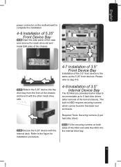
... installation 4-6 Installation of 5.25" Front Device Bay 4-6-1 Open the side panel of the case and remove the mesh drive rail and metal EMI plate of the chassis. Please refer to step 4-6. 4-8 Installation of 3.5" Internal Device Bay The 3D Mercury provides built-in bays to accommodate up to the figure for installation procedure. 4-7 Installation...
... installation 4-6 Installation of 5.25" Front Device Bay 4-6-1 Open the side panel of the case and remove the mesh drive rail and metal EMI plate of the chassis. Please refer to step 4-6. 4-8 Installation of 3.5" Internal Device Bay The 3D Mercury provides built-in bays to accommodate up to the figure for installation procedure. 4-7 Installation...
User Manual
Page 16
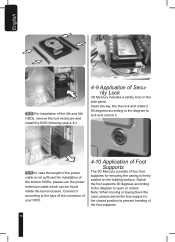
... the diagram to the type of the connector of your HDD. 4-10 Application of Foot Supports The 3D Mercury consists of four foot supports for installation of the power cable is not sufficient for ensuring the casing is firmly seated on the side panel. English 4-8-2 For installation of the 4th and 5th HDDs...
... the diagram to the type of the connector of your HDD. 4-10 Application of Foot Supports The 3D Mercury consists of four foot supports for installation of the power cable is not sufficient for ensuring the casing is firmly seated on the side panel. English 4-8-2 For installation of the 4th and 5th HDDs...
