User Manual
Page 2
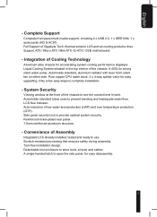
..., including power supply, hard disk, CD-ROM drive, motherboard, ventilator, etc, are not covered by failure to provide users with in a manner other than the designed purpose. 2. Incorrect connector installation may cause bodily harm or damage to the casing or other devices. 4. Gigabyte Tech. website. (http://www.gigabyte.com.tw) The following are not detached from the casing prior to the product...
..., including power supply, hard disk, CD-ROM drive, motherboard, ventilator, etc, are not covered by failure to provide users with in a manner other than the designed purpose. 2. Incorrect connector installation may cause bodily harm or damage to the casing or other devices. 4. Gigabyte Tech. website. (http://www.gigabyte.com.tw) The following are not detached from the casing prior to the product...
User Manual
Page 3
Installation Instruction 9 4-1 Installation of Power Supply 9 4-2 Installation of Motherboard 11 4-3 Installation of Add on Card 12 4-4 Installation of Front Multi-Media I/O Ports 13 4-5 Connection of Fan Power Cables 14 4-6 Installation of 5.25" Front Device Bay 15 4-7 Installation of 3.5" Front Device Bay 15 4-8 Installation of 3.5" Internal Device Bay 15 4-9 Application of Security Lock 16 4-10 Application of Foot Supports 16 4-11 Application of Transparent Side Panel 17 4-12 Application of Contents 1. Specification Features...
Installation Instruction 9 4-1 Installation of Power Supply 9 4-2 Installation of Motherboard 11 4-3 Installation of Add on Card 12 4-4 Installation of Front Multi-Media I/O Ports 13 4-5 Connection of Fan Power Cables 14 4-6 Installation of 5.25" Front Device Bay 15 4-7 Installation of 3.5" Front Device Bay 15 4-8 Installation of 3.5" Internal Device Bay 15 4-9 Application of Security Lock 16 4-10 Application of Foot Supports 16 4-11 Application of Transparent Side Panel 17 4-12 Application of Contents 1. Specification Features...
User Manual
Page 4
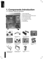
... and PCI Slot panel 1 4. 5.25" Front Device Bay 4 5. 3.5" Front Device Bay 6. 3.5" Internal Device Bay 7. Gigabyte Liquid Coolant x 2 Power Supply Bay 2. Tool Enclosure 5 2 3 6 8 7 a. AM2 Water block bracket i. k. Motherboard Securing Screw x 12 g. Power Supply Securing screw x 4 h. Extended screw for securing power sup- 4 ply retainer plate. Power Extension Cable x 2 c. 3.5" device Securing Runner x 10 d. Foot Support 8. Key x 2 e. j. Extended power supply retainer plate. PCI Tool-Free Fastener 3. Components Introduction 1-1 Casing's Internal...
... and PCI Slot panel 1 4. 5.25" Front Device Bay 4 5. 3.5" Front Device Bay 6. 3.5" Internal Device Bay 7. Gigabyte Liquid Coolant x 2 Power Supply Bay 2. Tool Enclosure 5 2 3 6 8 7 a. AM2 Water block bracket i. k. Motherboard Securing Screw x 12 g. Power Supply Securing screw x 4 h. Extended screw for securing power sup- 4 ply retainer plate. Power Extension Cable x 2 c. 3.5" device Securing Runner x 10 d. Foot Support 8. Key x 2 e. j. Extended power supply retainer plate. PCI Tool-Free Fastener 3. Components Introduction 1-1 Casing's Internal...

User Manual
Page 5
English 9. Power SW/Reset SW/HDD LED Connector f. USB 2.0 x 2 b. IEEE1394 (Multi-connectors) d. 3-Pin Fan Connector e. Front Cable Kit a. Audio (HD & AC97) c. Motherboard 2-pin connector and 4-pin connector to power supply. 1-2 Front, Rear, and Left Side Panel Structure a) Left Side Panel Side Grill for LCS air intake Latch Left Side Panel Security Lock Transparent/Mesh Side Panel 5
English 9. Power SW/Reset SW/HDD LED Connector f. USB 2.0 x 2 b. IEEE1394 (Multi-connectors) d. 3-Pin Fan Connector e. Front Cable Kit a. Audio (HD & AC97) c. Motherboard 2-pin connector and 4-pin connector to power supply. 1-2 Front, Rear, and Left Side Panel Structure a) Left Side Panel Side Grill for LCS air intake Latch Left Side Panel Security Lock Transparent/Mesh Side Panel 5
User Manual
Page 6
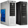
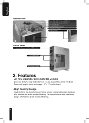
... easy installation and service, support SLI, Cross Fire Dual/ Quad multi-graphic cards, and support 12" x 13" motherboard. - top-class full tower thermal solution casing Lightweight aluminum alloy with hair-line brush anodized finishing Full-open aluminum side panel door design, with hair-line brush anodized finishing. 6 Features - High Quality Design Gigabyte Tech. English b) Front Panel Power / Reset Switches and LED light LCS radiator fan speed...
... easy installation and service, support SLI, Cross Fire Dual/ Quad multi-graphic cards, and support 12" x 13" motherboard. - top-class full tower thermal solution casing Lightweight aluminum alloy with hair-line brush anodized finishing Full-open aluminum side panel door design, with hair-line brush anodized finishing. 6 Features - High Quality Design Gigabyte Tech. English b) Front Panel Power / Reset Switches and LED light LCS radiator fan speed...
User Manual
Page 7
... of Cooling Technology Aluminum alloy chassis for easy upgrading. thermal solution LCS and air-cooling products lines Support ATX / Micro ATX / Mini ATX / E-ATX / CEB motherboard. - Automobile standard, aluminum radiator with dual 12cm silent fan on either side. Pure copper CPU water block. 2 x 4-way splitter valve for accelerating system cooling performance Gigabyte Liquid Cooling System situated in tank...
... of Cooling Technology Aluminum alloy chassis for easy upgrading. thermal solution LCS and air-cooling products lines Support ATX / Micro ATX / Mini ATX / E-ATX / CEB motherboard. - Automobile standard, aluminum radiator with dual 12cm silent fan on either side. Pure copper CPU water block. 2 x 4-way splitter valve for accelerating system cooling performance Gigabyte Liquid Cooling System situated in tank...
User Manual
Page 9
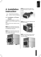
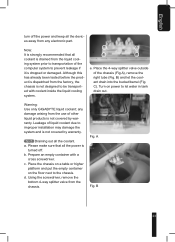
... 4. Installation Instruction 4-1-3 Secure the power supply onto the retainer plate, by unlatching the side panel. 4-1-2 Remove the thumb screws of the power supply retainer plate at the back of the chassis and remove. 4-1-5 Use the thumb screws to secure the power supply retainer plate to set the chassis upright on the table. Please follow the reference sections in the power supply from the rear of the chassis. 4-1-1 Remove...
... 4. Installation Instruction 4-1-3 Secure the power supply onto the retainer plate, by unlatching the side panel. 4-1-2 Remove the thumb screws of the power supply retainer plate at the back of the chassis and remove. 4-1-5 Use the thumb screws to secure the power supply retainer plate to set the chassis upright on the table. Please follow the reference sections in the power supply from the rear of the chassis. 4-1-1 Remove...

User Manual
Page 10
English 4-1-6 If a longer power supply is used which obstructs the product's sliding through the rear, please install the power according to the coolant tank. 4-1-7a Remove the thumb screws of the side panels and detach both side panels. 4-1-7b Remove the thumb screws of the power retainer plate at the rear and two on the top cover of the chassis, two at...
English 4-1-6 If a longer power supply is used which obstructs the product's sliding through the rear, please install the power according to the coolant tank. 4-1-7a Remove the thumb screws of the side panels and detach both side panels. 4-1-7b Remove the thumb screws of the power retainer plate at the rear and two on the top cover of the chassis, two at...

User Manual
Page 11
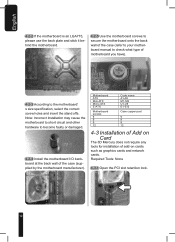
... panel, total of 5 screws.) 4-1-7i Reverse the steps to reassemble the parts 4-2 Installation of Motherboard 3D Mercury can support ATX / Micro ATX / Mini ATX / E-ATX / CEB Please confirm the motherboard screw holes locations and size specification before installation Required Tools: Screwdriver, stand offs, and the motherboard screws 4-1-7g Gently lift the liquid cooling system tray and insert the power supply through the rear chassis...
... panel, total of 5 screws.) 4-1-7i Reverse the steps to reassemble the parts 4-2 Installation of Motherboard 3D Mercury can support ATX / Micro ATX / Mini ATX / E-ATX / CEB Please confirm the motherboard screw holes locations and size specification before installation Required Tools: Screwdriver, stand offs, and the motherboard screws 4-1-7g Gently lift the liquid cooling system tray and insert the power supply through the rear chassis...
User Manual
Page 12
... specification, select the correct screw holes and insert the stand offs. Motherboard ATX Mini ATX Micro ATX E-ATX Motherboard screws 9 9 9 12 Code name A1-A9 M1-M9 U1-U9 E1-E12 Case copper post 9 9 9 12 4-3 Installation of Add on Card The 3D Mercury does not require any tools for installation of the case (supplied by the motherboard manufacturer). Required Tools: None 4-3-1 Open the PCI...
... specification, select the correct screw holes and insert the stand offs. Motherboard ATX Mini ATX Micro ATX E-ATX Motherboard screws 9 9 9 12 Code name A1-A9 M1-M9 U1-U9 E1-E12 Case copper post 9 9 9 12 4-3 Installation of Add on Card The 3D Mercury does not require any tools for installation of the case (supplied by the motherboard manufacturer). Required Tools: None 4-3-1 Open the PCI...
User Manual
Page 13
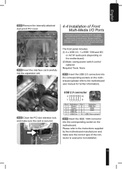
... motherboard) (2) Basic casing power switch control cable kit Required Tools: None 4-4-1 Insert the USB 2.0 connectors into the corresponding sockets on the motherboard. Please refer to the instructions supplied by the motherboard manufacturer and make sure the card is used prior to the motherboard user manual for further information). English 4-3-2 Remove the internally attached dust proof PCI cover. 4-3-3 Insert the interface card carefully into the expansion slot. 4-4 Installation...
... motherboard) (2) Basic casing power switch control cable kit Required Tools: None 4-4-1 Insert the USB 2.0 connectors into the corresponding sockets on the motherboard. Please refer to the instructions supplied by the motherboard manufacturer and make sure the card is used prior to the motherboard user manual for further information). English 4-3-2 Remove the internally attached dust proof PCI cover. 4-3-3 Insert the interface card carefully into the expansion slot. 4-4 Installation...

User Manual
Page 14
... cable kit. Plug the 3-pin connector into the corresponding socket on the mother- LED Brown (+)/White (-) 4-4-5 Power switch connector, LCS power supply (including LCS emergency shutdown). Please read the motherboard user manual supplied by the motherboard manufacturer 4-5 Connection of Fan Power Cables The 3D Mercury has one 12cm silent, blue LED cooling fan at the front and two at the rear Pin Definition Pin Definition 1 MIC2_L...
... cable kit. Plug the 3-pin connector into the corresponding socket on the mother- LED Brown (+)/White (-) 4-4-5 Power switch connector, LCS power supply (including LCS emergency shutdown). Please read the motherboard user manual supplied by the motherboard manufacturer 4-5 Connection of Fan Power Cables The 3D Mercury has one 12cm silent, blue LED cooling fan at the front and two at the rear Pin Definition Pin Definition 1 MIC2_L...
User Manual
Page 15
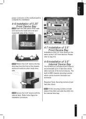
... runners (2 per hard disc drive) 4-8-1 Fit the securing runners on the motherboard to step 4-6. 4-8 Installation of 3.5" Internal Device Bay The 3D Mercury provides built-in the black tool enclosure. Please refer to complete the installation 4-6 Installation of 5.25" Front Device Bay 4-6-1 Open the side panel of the case and remove the mesh drive rail and metal EMI plate of the chassis. English power connector on both...
... runners (2 per hard disc drive) 4-8-1 Fit the securing runners on the motherboard to step 4-6. 4-8 Installation of 3.5" Internal Device Bay The 3D Mercury provides built-in the black tool enclosure. Please refer to complete the installation 4-6 Installation of 5.25" Front Device Bay 4-6-1 Open the side panel of the case and remove the mesh drive rail and metal EMI plate of the chassis. English power connector on both...
User Manual
Page 16
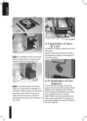
... Application of Foot Supports The 3D Mercury consists of four foot supports for installation of the foot supports. 16 Insert the key into the lock and rotate it . 4-8-3 In case the length of the power cable is not sufficient for ensuring the casing is firmly seated on the side panel. English 4-8-2 For installation of the 4th and 5th HDDs, remove the tool...
... Application of Foot Supports The 3D Mercury consists of four foot supports for installation of the foot supports. 16 Insert the key into the lock and rotate it . 4-8-3 In case the length of the power cable is not sufficient for ensuring the casing is firmly seated on the side panel. English 4-8-2 For installation of the 4th and 5th HDDs, remove the tool...

User Manual
Page 17
... grid. 4-12 Application of Liquid Cooling System 4-12-1 CPU water block installation Warning: Be sure to remove the "CAUTION" sticker from the carton box and remove the plastic protection layer. Take the transparent side panel window out from the bottom of Transparent Side Panel Required Tools: Cross screwdriver, transparent side panel window. c. b. Spread the thermal paste evenly on the...
... grid. 4-12 Application of Liquid Cooling System 4-12-1 CPU water block installation Warning: Be sure to remove the "CAUTION" sticker from the carton box and remove the plastic protection layer. Take the transparent side panel window out from the bottom of Transparent Side Panel Required Tools: Cross screwdriver, transparent side panel window. c. b. Spread the thermal paste evenly on the...
User Manual
Page 20
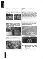
... fan into the tubes. a: 3-pin CPU fan socket / Fig. Please remove the lid on the top of the chassis and check the coolant level gauge on the front panel of the power supply. 4-13 4-way Splitter Valve Instruction and User Manual Note: Gigabyte Blue Eye and Chipset 20 Turn on the power until all the coolant drains into the CPU fan socket on to the motherboard...
... fan into the tubes. a: 3-pin CPU fan socket / Fig. Please remove the lid on the top of the chassis and check the coolant level gauge on the front panel of the power supply. 4-13 4-way Splitter Valve Instruction and User Manual Note: Gigabyte Blue Eye and Chipset 20 Turn on the power until all the coolant drains into the CPU fan socket on to the motherboard...

User Manual
Page 21
... connect the other side with the inlet of the chipset water block and fasten with tube clips. 21 Warning: Please make sure that the PC Power is turned off prior to the inlet of the VGA Blue Eye and fasten with tube clips. 4-13-4 Cut a tube into suitable size, connect one... side of the tube with the second splitter on the power at this moment and make sure that the valves are used as examples. Please do not switch on the 4-way splitter valve (1) and connect the other side to installation. 4-13-1 Remove the caps and tube clips from the 4-way splitter valve.
... connect the other side with the inlet of the chipset water block and fasten with tube clips. 21 Warning: Please make sure that the PC Power is turned off prior to the inlet of the VGA Blue Eye and fasten with tube clips. 4-13-4 Cut a tube into suitable size, connect one... side of the tube with the second splitter on the power at this moment and make sure that the valves are used as examples. Please do not switch on the 4-way splitter valve (1) and connect the other side to installation. 4-13-1 Remove the caps and tube clips from the 4-way splitter valve.
User Manual
Page 23
... to improper installation may damage the system and is not covered by warranty. Although this has already been tested before the product is dispatched from the factory, the chassis is not covered by warranty. 4-13-8 Draining out all the power is dropped or damaged. a. b. A Fig. English turn off . Fig. Using the screwdriver, remove the bottom...
... to improper installation may damage the system and is not covered by warranty. Although this has already been tested before the product is dispatched from the factory, the chassis is not covered by warranty. 4-13-8 Draining out all the power is dropped or damaged. a. b. A Fig. English turn off . Fig. Using the screwdriver, remove the bottom...

User Manual
Page 24
... air inside the tubes. d. c. It is to transport the chassis or replace parts that need tools for this. You will need to be replaced. 4-14 Liquid Cooling System Maintenance 4-14-1 If If the coolant level is now safe to low, remove the top lid and, after refilling coolant, secure the lid back... on either side of the chassis. 24 Please use the above...
... air inside the tubes. d. c. It is to transport the chassis or replace parts that need tools for this. You will need to be replaced. 4-14 Liquid Cooling System Maintenance 4-14-1 If If the coolant level is now safe to low, remove the top lid and, after refilling coolant, secure the lid back... on either side of the chassis. 24 Please use the above...

User Manual
Page 26
... the front fan holder. Replace the parts that hold the front panel onto the chassis, and remove the front panel. GIGABYTE VGA Air Cooler - Open the two side panels. Recommended parts to reassemble. GIGABYTE Radiator c. After cleaning the fan filter, reverse steps to purchase - Take out the fan holder and separate the fan holder from the fan. 26 a. GIGABYTE Blue Eye (VGA Liquid Cooling) - Remove the pump...
... the front fan holder. Replace the parts that hold the front panel onto the chassis, and remove the front panel. GIGABYTE VGA Air Cooler - Open the two side panels. Recommended parts to reassemble. GIGABYTE Radiator c. After cleaning the fan filter, reverse steps to purchase - Take out the fan holder and separate the fan holder from the fan. 26 a. GIGABYTE Blue Eye (VGA Liquid Cooling) - Remove the pump...
