
Installation Guide
Page 1
NetworX™ Series NX-320E REMOTE POWER SUPPLY Installation and Startup
NetworX™ Series NX-320E REMOTE POWER SUPPLY Installation and Startup

Installation Guide
Page 2
...888-437-3287 800-547-2556 2 NX-320E Power Supply This document shall not be disclosed to assist that are not covered sufficiently for detailed warranty information. © 2005 GE Security All rights reserved. This document contains proprietary information of GE Security. Please refer to GE Security, Gladewater, Texas, USA. If ...reproduced in whole or in part nor shall its customer solely to any third party without the written approval of GE Security, USA and is desired or if particular problems arise that customer in equipment nor to provide every possible contingency to...
...888-437-3287 800-547-2556 2 NX-320E Power Supply This document shall not be disclosed to assist that are not covered sufficiently for detailed warranty information. © 2005 GE Security All rights reserved. This document contains proprietary information of GE Security. Please refer to GE Security, Gladewater, Texas, USA. If ...reproduced in whole or in part nor shall its customer solely to any third party without the written approval of GE Security, USA and is desired or if particular problems arise that customer in equipment nor to provide every possible contingency to...
Installation Guide
Page 3
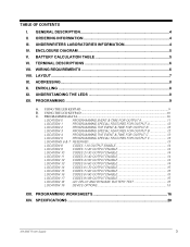
... TEST 15 LOCATION 19 DEVICE OPTIONS 15 XIII. ADDRESSING...8 X. ENROLLING ...8 XI. WIRING REQUIREMENTS 6 VIII. USING THE LED KEYPAD ...9 B. USING THE LCD KEYPAD ...10 C. SPECIFICATIONS 20 NX-320E Power Supply 3 ORDERING INFORMATION 4 III. LAYOUT...7 IX. UNDERSTANDING THE LEDS 8 XII.
... TEST 15 LOCATION 19 DEVICE OPTIONS 15 XIII. ADDRESSING...8 X. ENROLLING ...8 XI. WIRING REQUIREMENTS 6 VIII. USING THE LED KEYPAD ...9 B. USING THE LCD KEYPAD ...10 C. SPECIFICATIONS 20 NX-320E Power Supply 3 ORDERING INFORMATION 4 III. LAYOUT...7 IX. UNDERSTANDING THE LEDS 8 XII.
Installation Guide
Page 4
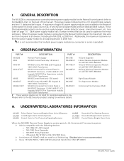
... Units When the NX-320E Remote Power Supply is used as part of which 24 are programmable and 8 are UL listed for warranty details. Each power supply module has a Tamper terminal that multiple power supply modules be used to the GE Security product catalog for...wired transformer (Part #T-0002) 4 NX-320E Power Supply GENERAL DESCRIPTION The NX-320E is 2500 feet. A maximum of eight (8) power supply modules can be used for the NetworX control panels (refer to all devices, including the NX-320E, is a microprocessor controlled remote power supply module for all outgoing devices is...
... Units When the NX-320E Remote Power Supply is used as part of which 24 are programmable and 8 are UL listed for warranty details. Each power supply module has a Tamper terminal that multiple power supply modules be used to the GE Security product catalog for...wired transformer (Part #T-0002) 4 NX-320E Power Supply GENERAL DESCRIPTION The NX-320E is 2500 feet. A maximum of eight (8) power supply modules can be used for the NetworX control panels (refer to all devices, including the NX-320E, is a microprocessor controlled remote power supply module for all outgoing devices is...

Installation Guide
Page 5
... AH 51 AH 34 AH 17 AH 51 AH 34 AH 17 AH ALARM CURRENT 600 mA 1 Amp 1 Amp 1 Amp 1 Amp 1 Amp 1 Amp 1 Amp 1 Amp NX-320E Power Supply 5 The half-moon protrusion will be in place. Diagram 3: The PC board should reach through the notch that the insertion points have been constructed. Diagram... not require force. Once mounted, screw it in the large hole. The smaller hole is for either vertical or horizontal placement of the guide to secure it in the top insertion point, grooved edge downward. Diagram 2: Place the first black plastic PCB guide in...
... AH 51 AH 34 AH 17 AH 51 AH 34 AH 17 AH ALARM CURRENT 600 mA 1 Amp 1 Amp 1 Amp 1 Amp 1 Amp 1 Amp 1 Amp 1 Amp NX-320E Power Supply 5 The half-moon protrusion will be in place. Diagram 3: The PC board should reach through the notch that the insertion points have been constructed. Diagram... not require force. Once mounted, screw it in the large hole. The smaller hole is for either vertical or horizontal placement of the guide to secure it in the top insertion point, grooved edge downward. Diagram 2: Place the first black plastic PCB guide in...

Installation Guide
Page 6
... output current limited to 1.9 Amps. Ê Common terminal for any device powered from the NX-320E to Compatibility chart on page 7. WIRING REQUIREMENTS Table VII:1 For UL COMMERCIAL FIRE installations, a minimum of the power to the NetworX control panel COMMON terminal. This terminal supplies the common side of 18 AWG shall be used . Shielded wire is...
... output current limited to 1.9 Amps. Ê Common terminal for any device powered from the NX-320E to Compatibility chart on page 7. WIRING REQUIREMENTS Table VII:1 For UL COMMERCIAL FIRE installations, a minimum of the power to the NetworX control panel COMMON terminal. This terminal supplies the common side of 18 AWG shall be used . Shielded wire is...

Installation Guide
Page 7
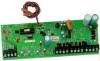
VIII. LAYOUT NX-320E Power Supply Recommended: Basler Model BE30614001 120VAC 60Hz 16.5VAC 50VA Class... 1 7 IT IS PULSED (TEMPORAL) DURING A FIRE ALARM AND STEADY DURING A BURGLAR ALARM. CONTROL PANEL DRAWS 50MA STANDBY POWER. CONNECT TO CONTROL PANEL UL Installations: The Class 2, Class 3, and powerlimited fire alarm circuits must be installed using FPL, FPLP... or CL3P, or substitute cable permitted by National Electrical Code ANSI/NFPA70 and the Class 2, Class 3 and power-limited fire alarm circuit conductors extending beyond the cable jacket must be separated a minimum of ¼ inch or...
VIII. LAYOUT NX-320E Power Supply Recommended: Basler Model BE30614001 120VAC 60Hz 16.5VAC 50VA Class... 1 7 IT IS PULSED (TEMPORAL) DURING A FIRE ALARM AND STEADY DURING A BURGLAR ALARM. CONTROL PANEL DRAWS 50MA STANDBY POWER. CONNECT TO CONTROL PANEL UL Installations: The Class 2, Class 3, and powerlimited fire alarm circuits must be installed using FPL, FPLP... or CL3P, or substitute cable permitted by National Electrical Code ANSI/NFPA70 and the Class 2, Class 3 and power-limited fire alarm circuit conductors extending beyond the cable jacket must be separated a minimum of ¼ inch or...

Installation Guide
Page 8
... seconds, during which provide valuable information about its memory the presence of the NetworX control panel, and when the Program Mode is exited, it is transmitted out from the NX-320E. The following chart furnishes the indications of this manual). 8 NX-320E Power Supply DS3 Flashes during the enrolling process. DS4 Used for hardware, and will be...
... seconds, during which provide valuable information about its memory the presence of the NetworX control panel, and when the Program Mode is exited, it is transmitted out from the NX-320E. The following chart furnishes the indications of this manual). 8 NX-320E Power Supply DS3 Flashes during the enrolling process. DS4 Used for hardware, and will be...

Installation Guide
Page 9
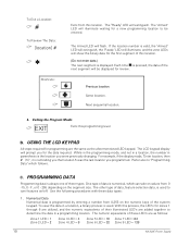
...), and remain in the Program Mode and ready to select the module to be entered. 3. If the location is saved. The keypad will illuminate steady. NX-320E Power Supply 9 To Enter a Location: & [location] # The Armed LED will flash. NOTE: These steps are now in that segment awaiting a valid entry. Entering the Program Mode & Á...
...), and remain in the Program Mode and ready to select the module to be entered. 3. If the location is saved. The keypad will illuminate steady. NX-320E Power Supply 9 To Enter a Location: & [location] # The Armed LED will flash. NOTE: These steps are now in that segment awaiting a valid entry. Entering the Program Mode & Á...
Installation Guide
Page 10
... the same as follows: Zone 1 LED = 1 Zone 2 LED = 2 Zone 3 LED = 4 Zone 4 LED = 8 Zone 5 LED = 16 Zone 7 LED = 64 Zone 6 LED = 32 Zone 8 LED = 128 10 NX-320E Power Supply C. F, or 0 - 255 depending on values from 0-255 on /off. The other type of three types. Numerical Data Numerical data is valid, the "Armed" LED will...
... the same as follows: Zone 1 LED = 1 Zone 2 LED = 2 Zone 3 LED = 4 Zone 4 LED = 8 Zone 5 LED = 16 Zone 7 LED = 64 Zone 6 LED = 32 Zone 8 LED = 128 10 NX-320E Power Supply C. F, or 0 - 255 depending on values from 0-255 on /off. The other type of three types. Numerical Data Numerical data is valid, the "Armed" LED will...

Installation Guide
Page 11
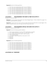
... to the "feature number" within one second. You will toggle (on the keypad. When you are now ready to enter another programming location. NX-320E Power Supply 11 The LED=s for the specific events that location. This will remain activated when an output triggers. Table XII:1 # Event # Event #... Event 0 Always On 11 Smoke Power Reset 22 Disarmed 1 AC Fail (control or exp.) Does not follow AC Fail delay time 12 Yelping Siren 23 Ready to Arm 2 Low...
... to the "feature number" within one second. You will toggle (on the keypad. When you are now ready to enter another programming location. NX-320E Power Supply 11 The LED=s for the specific events that location. This will remain activated when an output triggers. Table XII:1 # Event # Event #... Event 0 Always On 11 Smoke Power Reset 22 Disarmed 1 AC Fail (control or exp.) Does not follow AC Fail delay time 12 Yelping Siren 23 Ready to Arm 2 Low...

Installation Guide
Page 12
... should stop time when a code is entered. 4 = "On" for inverted output. 5 = "On" disables output during listen-in (only events 12-16). 6 = Reserved. 7 = Reserved. 8 = Reserved. 12 NX-320E Power Supply "Off" for timed. 3 = "On" if output should stop time when a code is entered. 4 = "On" for inverted output. 5 = "On" disables output during listen-in (only events...
... should stop time when a code is entered. 4 = "On" for inverted output. 5 = "On" disables output during listen-in (only events 12-16). 6 = Reserved. 7 = Reserved. 8 = Reserved. 12 NX-320E Power Supply "Off" for timed. 3 = "On" if output should stop time when a code is entered. 4 = "On" for inverted output. 5 = "On" disables output during listen-in (only events...
Installation Guide
Page 13
... Partition 6. 7 = "On" if the event should activate when it occurs in Partition 7. 8 = "On" if the event should activate when it occurs in Partition 8. LOCATIONS 6 & 7 RESERVED NX-320E Power Supply 13 Segment 2 selects the following partitions: 1 = "On" if the event should activate when it occurs in Partition 1. 2 = "On" if the event should activate when it...
... Partition 6. 7 = "On" if the event should activate when it occurs in Partition 7. 8 = "On" if the event should activate when it occurs in Partition 8. LOCATIONS 6 & 7 RESERVED NX-320E Power Supply 13 Segment 2 selects the following partitions: 1 = "On" if the event should activate when it occurs in Partition 1. 2 = "On" if the event should activate when it...

Installation Guide
Page 14
... feature selection data) When activating outputs with a user code (event #30), location 13 can be used to user 1; C (see Table XII:2 on page 14). 14 NX-320E Power Supply Segment 1 corresponds to restrict certain codes from activating certain outputs. "Off" if it will not. 3 "On" if code will activate Output B; Segment 1 corresponds to restrict...
... feature selection data) When activating outputs with a user code (event #30), location 13 can be used to user 1; C (see Table XII:2 on page 14). 14 NX-320E Power Supply Segment 1 corresponds to restrict certain codes from activating certain outputs. "Off" if it will not. 3 "On" if code will activate Output B; Segment 1 corresponds to restrict...
Installation Guide
Page 15
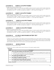
...report Low Battery to the central station. 4 On enables Siren Tamper/Trouble reporting If enabled, the power supply module will report a Siren Tamper to the central station. 5-8 Reserved NX-320E Power Supply 15 Table XII:3 LED Description 1 On for the time programmed in Location 18. Segment 1 corresponds ...corresponds to user 70. Segment 10 corresponds to user 90. LOCATION 16 CODES 81-90 OUTPUT ENABLE (10 segments of the power supply module. LOCATION 19 DEVICE OPTIONS (8 segments of feature selection data) Location 19 is used to enable various system features of ...
...report Low Battery to the central station. 4 On enables Siren Tamper/Trouble reporting If enabled, the power supply module will report a Siren Tamper to the central station. 5-8 Reserved NX-320E Power Supply 15 Table XII:3 LED Description 1 On for the time programmed in Location 18. Segment 1 corresponds ...corresponds to user 70. Segment 10 corresponds to user 90. LOCATION 16 CODES 81-90 OUTPUT ENABLE (10 segments of the power supply module. LOCATION 19 DEVICE OPTIONS (8 segments of feature selection data) Location 19 is used to enable various system features of ...

Installation Guide
Page 16
...is entered; PROGRAMMING WORKSHEETS (Defaults are printed in bold italics text.) At Default: Output A = AUX POWER Output B = AUX POWER Output C = SMOKE POWER LOC 0 1 2 3 4 5 6 & 7 PAGE 11 12 12 12 13 13 13 DESCRIPTION...Partition 7 8 = Partition 8 _ _ 5 = Partition 5 6 = Partition 6 7 = Partition 7 8 = Partition 8 _ _ 5 = Partition 5 6 = Partition 6 7 = Partition 7 8 = Partition 8 16 NX-320E Power Supply "Off" for 3 = Partition 3 timed. 4 = Partition 4 3 = "On" if output should stop time when a code is entered. 4 = "On" for inverted output. 5 = "On" disables output during listen...
...is entered; PROGRAMMING WORKSHEETS (Defaults are printed in bold italics text.) At Default: Output A = AUX POWER Output B = AUX POWER Output C = SMOKE POWER LOC 0 1 2 3 4 5 6 & 7 PAGE 11 12 12 12 13 13 13 DESCRIPTION...Partition 7 8 = Partition 8 _ _ 5 = Partition 5 6 = Partition 6 7 = Partition 7 8 = Partition 8 _ _ 5 = Partition 5 6 = Partition 6 7 = Partition 7 8 = Partition 8 16 NX-320E Power Supply "Off" for 3 = Partition 3 timed. 4 = Partition 4 3 = "On" if output should stop time when a code is entered. 4 = "On" for inverted output. 5 = "On" disables output during listen...

Installation Guide
Page 17
... #C 3 3 3 3 3 3 3 3 3 3 17 15 Codes 91-99 Output Enable (Circle the numbers to program) User 91 92 93 94 95 96 97 98 99 Output #A 1 1 1 1 1 1 1 1 1 Output #B 2 2 2 2 2 2 2 2 2 Output #C 3 3 3 3 3 3 3 3 3 NX-320E Power Supply 17
... #C 3 3 3 3 3 3 3 3 3 3 17 15 Codes 91-99 Output Enable (Circle the numbers to program) User 91 92 93 94 95 96 97 98 99 Output #A 1 1 1 1 1 1 1 1 1 Output #B 2 2 2 2 2 2 2 2 2 Output #C 3 3 3 3 3 3 3 3 3 NX-320E Power Supply 17

Installation Guide
Page 18
LOC 18 19 PAGE 15 15 DESCRIPTION A/C Delay (in minutes) Dynamic Battery Test (in minutes) Device Options (Circle the numbers to program) 1=On for AC report always sent; Off follows control 2=On enables periodic battery test 3=On enables low battery reporting 4=On enables siren tamper/trouble reporting DEFAULT 5 0 5=Reserved 6=Reserved 7=Reserved 8=Reserved DATA ___ ___ 18 NX-320E Power Supply
LOC 18 19 PAGE 15 15 DESCRIPTION A/C Delay (in minutes) Dynamic Battery Test (in minutes) Device Options (Circle the numbers to program) 1=On for AC report always sent; Off follows control 2=On enables periodic battery test 3=On enables low battery reporting 4=On enables siren tamper/trouble reporting DEFAULT 5 0 5=Reserved 6=Reserved 7=Reserved 8=Reserved DATA ___ ___ 18 NX-320E Power Supply