
Installation Guide
Page 2
...: www.gesecurity.com Technical Support Sales & Literature 888-437-3287 800-547-2556 2 NX-320E Power Supply This document shall not be referred to assist that are not covered sufficiently for detailed warranty information. This document contains proprietary information of GE Security. These instructions do not purport to cover all details or variations in the installation...
...: www.gesecurity.com Technical Support Sales & Literature 888-437-3287 800-547-2556 2 NX-320E Power Supply This document shall not be referred to assist that are not covered sufficiently for detailed warranty information. This document contains proprietary information of GE Security. These instructions do not purport to cover all details or variations in the installation...
Installation Guide
Page 4
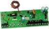
... is connected to the NetworX control panel, the maximum total wire run from the panel to Compatibility chart on page 11). Additionally, the maximum total wire run from the power supply module to the GE Security product catalog for residential applications only. GENERAL DESCRIPTION The NX-320E is compatible with the following devices: o NX-148E-CF LCD keypad...
... is connected to the NetworX control panel, the maximum total wire run from the panel to Compatibility chart on page 11). Additionally, the maximum total wire run from the power supply module to the GE Security product catalog for residential applications only. GENERAL DESCRIPTION The NX-320E is compatible with the following devices: o NX-148E-CF LCD keypad...

Installation Guide
Page 5
... 17 AH 51 AH 34 AH 17 AH ALARM CURRENT 600 mA 1 Amp 1 Amp 1 Amp 1 Amp 1 Amp 1 Amp 1 Amp 1 Amp NX-320E Power Supply 5 Diagram 2: Place the first black plastic PCB guide in securely. The smaller hole is for either vertical or horizontal placement of both guides. It does not require force. The second PCB... board should reach through the notch that the insertion points have been constructed. The half-moon protrusion will be positioned opposite of the guide to secure it in the top insertion point, grooved edge downward.
... 17 AH 51 AH 34 AH 17 AH ALARM CURRENT 600 mA 1 Amp 1 Amp 1 Amp 1 Amp 1 Amp 1 Amp 1 Amp 1 Amp NX-320E Power Supply 5 Diagram 2: Place the first black plastic PCB guide in securely. The smaller hole is for either vertical or horizontal placement of both guides. It does not require force. The second PCB... board should reach through the notch that the insertion points have been constructed. The half-moon protrusion will be positioned opposite of the guide to secure it in the top insertion point, grooved edge downward.