
Installation Instructions
Page 1
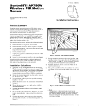
... ITI Part No. 60-880-95 Document Number: 466-1851 Rev. This wireless motion sensor includes the following features: ‰ Field-selectable coverage area; 33 or 50 feet ‰ Field-selectable sensitivity modes; 2-pulse or 4-pulse ‰ 135-second transmitter lockout time after an alarm that helps extend battery life ‰ Cover-activated tamper ‰ Supervisory signal transmitted every 64 minutes to the control panel ‰ Sensor low battery reports (trouble...
... ITI Part No. 60-880-95 Document Number: 466-1851 Rev. This wireless motion sensor includes the following features: ‰ Field-selectable coverage area; 33 or 50 feet ‰ Field-selectable sensitivity modes; 2-pulse or 4-pulse ‰ 135-second transmitter lockout time after an alarm that helps extend battery life ‰ Cover-activated tamper ‰ Supervisory signal transmitted every 64 minutes to the control panel ‰ Sensor low battery reports (trouble...
Installation Instructions
Page 2
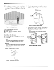
... to secure the sensor. 1RWH Avoid touching the mirror. Touch a grounded, bare metal surface before handling sensor circuit boards. Use wall anchors and screws to block any detection pattern directed at the top (see Figure 6). Mounting the Sensor ‰ For installations where pets are present, mount the sensor upside down on a flat wall or in a corner, using the appropriate mounting holes (see Figure 5). Leave the factory-installed...
... to secure the sensor. 1RWH Avoid touching the mirror. Touch a grounded, bare metal surface before handling sensor circuit boards. Use wall anchors and screws to block any detection pattern directed at the top (see Figure 6). Mounting the Sensor ‰ For installations where pets are present, mount the sensor upside down on a flat wall or in a corner, using the appropriate mounting holes (see Figure 5). Leave the factory-installed...
Installation Instructions
Page 3
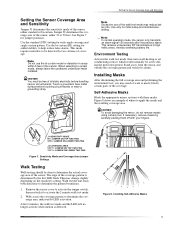
... be free of the sensor. Use the bi-curtain (BI) setting for added stability to help reduce false alarms. This mode requires intruders to determine the coverage area, indicated by the first LED flash. Touch a grounded, bare metal surface before handling sensor circuit boards. Stand away from both directions to mask (block) certain parts of the sensor. T = J U M P E R O N L O W E R T W O P IN S Figure 7. Remove the sensor cover to activate the tamper switch...
... be free of the sensor. Use the bi-curtain (BI) setting for added stability to help reduce false alarms. This mode requires intruders to determine the coverage area, indicated by the first LED flash. Touch a grounded, bare metal surface before handling sensor circuit boards. Stand away from both directions to mask (block) certain parts of the sensor. T = J U M P E R O N L O W E R T W O P IN S Figure 7. Remove the sensor cover to activate the tamper switch...

Installation Instructions
Page 4
... the panel into panel memory. Exit from program mode. Move across the detection pattern until the sensor LED turns on, then STOP your motion. 5. If the system does not respond, proceed to the specific panel installation instructions for complete programming information. 1. Use only exact replacement 3-volt lithium batteries (CR123A). &$87,21 You must be instructed to put the sensor in test mode. 4. Replace the sensor cover. 3. The end user should be done to the specific panel installation instructions for complete sensor testing...
... the panel into panel memory. Exit from program mode. Move across the detection pattern until the sensor LED turns on, then STOP your motion. 5. If the system does not respond, proceed to the specific panel installation instructions for complete programming information. 1. Use only exact replacement 3-volt lithium batteries (CR123A). &$87,21 You must be instructed to put the sensor in test mode. 4. Replace the sensor cover. 3. The end user should be done to the specific panel installation instructions for complete sensor testing...
Installation Instructions
Page 5
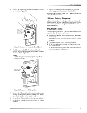
... activating the walk test mode. cuit board. 5 Figure 11.Removing the Transmitter Circuit Board 4. Troubleshooting Use the following guidelines if the system does not respond correctly when the sensor is activated. ‰ Check programming and re-program sensor into the sensor plastic. 7. Re-install the PIR circuit board into panel if necessary. ‰ Move the sensor to properly dispose of components) and install a new one, observing polarity...
... activating the walk test mode. cuit board. 5 Figure 11.Removing the Transmitter Circuit Board 4. Troubleshooting Use the following guidelines if the system does not respond correctly when the sensor is activated. ‰ Check programming and re-program sensor into the sensor plastic. 7. Re-install the PIR circuit board into panel if necessary. ‰ Move the sensor to properly dispose of components) and install a new one, observing polarity...
Installation Instructions
Page 6
... users' authority to the following two conditions: 1. Learn Mode Panels Power source: Two 3-volt lithium (CR123A) batteries Typical battery life: 2-4 years at 68° F (not verified by Interactive Technologies, Inc. These devices must accept any interference received, including interference that may not cause harmful interference. 2. FCC ID: B4Z-779A-PIR U.S. Operation is a trademark of Interlogix, Inc. 466-1851 Rev. Changes...
... users' authority to the following two conditions: 1. Learn Mode Panels Power source: Two 3-volt lithium (CR123A) batteries Typical battery life: 2-4 years at 68° F (not verified by Interactive Technologies, Inc. These devices must accept any interference received, including interference that may not cause harmful interference. 2. FCC ID: B4Z-779A-PIR U.S. Operation is a trademark of Interlogix, Inc. 466-1851 Rev. Changes...


