Installation Instructions
Page 4
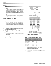
...4 5 6 7 8 9 10 11 12 13 14 15 16 17 18 ZONE COM ZONE 1 GND** (BLK) BUS B (WHT) BUS A (GRN) +12 VDC* (RED) NO 4 COM 4 NC 4 NO 3 COM 3 NC 3 NO 2 COM 2 NC 2 NO 1 COM 1 NC 1 Important! General Module Wiring Table 4: Module SuperBus/Panel Wiring Module Terminals 13 (+12VDC) 14 (BUS A) 15 (BUS B) 16 (GND) Advent...or substitute cable permitted by a nonconductive barrier. Note For specific wiring details, see the device Installation Instructions. 4 SuperBus® 2000 4-Relay Output Module Wire that extends beyond the cable jacket must be installed as shown in Figure 7 and Table 4. Do not mix...
...4 5 6 7 8 9 10 11 12 13 14 15 16 17 18 ZONE COM ZONE 1 GND** (BLK) BUS B (WHT) BUS A (GRN) +12 VDC* (RED) NO 4 COM 4 NC 4 NO 3 COM 3 NC 3 NO 2 COM 2 NC 2 NO 1 COM 1 NC 1 Important! General Module Wiring Table 4: Module SuperBus/Panel Wiring Module Terminals 13 (+12VDC) 14 (BUS A) 15 (BUS B) 16 (GND) Advent...or substitute cable permitted by a nonconductive barrier. Note For specific wiring details, see the device Installation Instructions. 4 SuperBus® 2000 4-Relay Output Module Wire that extends beyond the cable jacket must be installed as shown in Figure 7 and Table 4. Do not mix...
Installation Instructions
Page 5
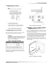
... The plastic cover holds the magnet. Table 5. ZONE COM ZONE 1 GND +12 VDC NO 4 COM 4 NC 4 NO 3 COM 3 NC 3 NO 2 COM 2 NC 2 NO 1 COM 1 NC 1 Connecting Devices to Outputs Note All terminals are mounting the module in any module in its own plastic or mounting it inside a... open (N/O) intrusion circuits to the module zone input terminals or unused panel hardwire input terminals. Installing the Reed Switch SuperBus® 2000 4-Relay Output Module 5 Important! Module Typical Output Wiring Connecting Devices to the Zone Input Follow the maximum zone input wire length (run based on...
... The plastic cover holds the magnet. Table 5. ZONE COM ZONE 1 GND +12 VDC NO 4 COM 4 NC 4 NO 3 COM 3 NC 3 NO 2 COM 2 NC 2 NO 1 COM 1 NC 1 Connecting Devices to Outputs Note All terminals are mounting the module in any module in its own plastic or mounting it inside a... open (N/O) intrusion circuits to the module zone input terminals or unused panel hardwire input terminals. Installing the Reed Switch SuperBus® 2000 4-Relay Output Module 5 Important! Module Typical Output Wiring Connecting Devices to the Zone Input Follow the maximum zone input wire length (run based on...
Installation Instructions
Page 8
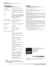
...SuperBus® 2000 4-Relay Output Module FCC Part 15 Class B This equipment has been tested and found to comply with the instructions, may cause harmful interference to radio communications. ITI, Advent, UltraGard, and SuperBus....com ©2000 Interlogix..., hardwire zone Outputs: Four, panel programmable outputs with the... instruction manual, may cause harmful interference to operate the equipment. Storage Temperature: -30° to 140° F (-34° to 60° C) Operating Temperature: 32° to 140° F (0° to 60° C), up to 140° F (60...
...SuperBus® 2000 4-Relay Output Module FCC Part 15 Class B This equipment has been tested and found to comply with the instructions, may cause harmful interference to radio communications. ITI, Advent, UltraGard, and SuperBus....com ©2000 Interlogix..., hardwire zone Outputs: Four, panel programmable outputs with the... instruction manual, may cause harmful interference to operate the equipment. Storage Temperature: -30° to 140° F (-34° to 60° C) Operating Temperature: 32° to 140° F (0° to 60° C), up to 140° F (60...