Installation Instructions
Page 1
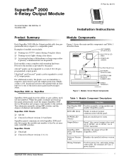
...) Indicates module power status. SuperBus® 2000 4-Relay Output Module 1 SuperBus® 2000 4-Relay Output Module ITI Part No. 60-770 Document Number: 466-1608 Rev. u Turning on ...security panel hardwire input zones. Advent® panels can be expanded to a compatible panel. Simply connect a UL listed reed switch to the module built-in zone input or to the module. B November 2000 8557109A.DS4 Installation Instructions Product Summary Module Components Each SuperBus 2000 4-Relay Output module adds four programmable relay outputs to a total of module uses include: u Turning...
...) Indicates module power status. SuperBus® 2000 4-Relay Output Module 1 SuperBus® 2000 4-Relay Output Module ITI Part No. 60-770 Document Number: 466-1608 Rev. u Turning on ...security panel hardwire input zones. Advent® panels can be expanded to a compatible panel. Simply connect a UL listed reed switch to the module built-in zone input or to the module. B November 2000 8557109A.DS4 Installation Instructions Product Summary Module Components Each SuperBus 2000 4-Relay Output module adds four programmable relay outputs to a total of module uses include: u Turning...
Installation Instructions
Page 3
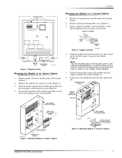
... 3. Turn the module upside down and line up and onto the cabinet side tab. PANEL END MODULE END 8573g64A.DSF Figure 5. Push the lower-right corner of the module onto the... and disconnect the backup battery. 2. Remove and discard the module cover (Figure 2). 3. Remove panel AC power and disconnect the backup battery(s). 2. Secure the back-plate to the cabinet using three ¼-inch... Cabinet SuperBus® 2000 4-Relay Output Module 3 Gently press the module up the holes on the top-left corner or center of the cabinet are designated for a receiver module, but if a receiver module is ...
... 3. Turn the module upside down and line up and onto the cabinet side tab. PANEL END MODULE END 8573g64A.DSF Figure 5. Push the lower-right corner of the module onto the... and disconnect the backup battery. 2. Remove and discard the module cover (Figure 2). 3. Remove panel AC power and disconnect the backup battery(s). 2. Secure the back-plate to the cabinet using three ¼-inch... Cabinet SuperBus® 2000 4-Relay Output Module 3 Gently press the module up the holes on the top-left corner or center of the cabinet are designated for a receiver module, but if a receiver module is ...
Installation Instructions
Page 4
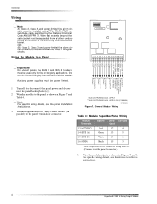
... by a nonconductive barrier. SUPPLY GND (COMMON) 9710G03A.DSF Figure 7. Turn off (or disconnect) the panel power and disconnect the panel backup battery(s). 2. General Module Wiring Table 4: Module SuperBus/Panel Wiring Module Terminals 13 (+12VDC) 14 (BUS A) 15 (BUS B) 16 (GND... specific wiring details, see the device Installation Instructions. 4 SuperBus® 2000 4-Relay Output Module SUPPLY **ALSO OUTPUT AND AUX. Wire the module outputs as shown in parallel) to a Panel ID: XXXXXXXX 1 2 3 4 5 6 7 8 9 10 11 12 13 14 15 16 17 18 ZONE COM ZONE 1 GND** (BLK) BUS B (WHT) BUS ...
... by a nonconductive barrier. SUPPLY GND (COMMON) 9710G03A.DSF Figure 7. Turn off (or disconnect) the panel power and disconnect the panel backup battery(s). 2. General Module Wiring Table 4: Module SuperBus/Panel Wiring Module Terminals 13 (+12VDC) 14 (BUS A) 15 (BUS B) 16 (GND... specific wiring details, see the device Installation Instructions. 4 SuperBus® 2000 4-Relay Output Module SUPPLY **ALSO OUTPUT AND AUX. Wire the module outputs as shown in parallel) to a Panel ID: XXXXXXXX 1 2 3 4 5 6 7 8 9 10 11 12 13 14 15 16 17 18 ZONE COM ZONE 1 GND** (BLK) BUS B (WHT) BUS ...
Installation Instructions
Page 6
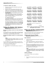
...with a 2.0K ohm (ITI part number 46-467) EOL resistor to the module ZONE 1 (17) and ZONE COMMON (18) terminals (Figure 9). On Concord (software versions 1.0-1.6) Systems: Connect... Figure 11. Verify that all wiring between the panel and module is correct. 6 SuperBus® 2000 4-Relay Output Module Setting the Module Unit Numbers To install the tamper reed switch: 1. Locate...Module Unit Number DIP Switch Settings (Non-SuperBus 2000 systems) On Concord (software version 2.0 or later) and Advent Panels Locate the DIP switches on for automatic). The unit number will turn on the module...
...with a 2.0K ohm (ITI part number 46-467) EOL resistor to the module ZONE 1 (17) and ZONE COMMON (18) terminals (Figure 9). On Concord (software versions 1.0-1.6) Systems: Connect... Figure 11. Verify that all wiring between the panel and module is correct. 6 SuperBus® 2000 4-Relay Output Module Setting the Module Unit Numbers To install the tamper reed switch: 1. Locate...Module Unit Number DIP Switch Settings (Non-SuperBus 2000 systems) On Concord (software version 2.0 or later) and Advent Panels Locate the DIP switches on for automatic). The unit number will turn on the module...

Installation Instructions
Page 7
...software versions only momentarily, 1.0-1.6) and UltraGard systems, activate randomly, check for configuring module outputs, adding (learning) hardwire sensors, and testing. necting and reconnecting panel power. 3. Module Zone input 1. Enter Item Number 48001 to "A." 4. Connect the panel battery and restore...Installation Instructions). 2. SuperBus® 2000 4-Relay Output Module 7 Press 8 for incorrect wiring con- The red BUS LED 1. If the LED still doesn't flash, replace the module. Connect the panel battery(s) and restore panel AC power. Turn on or the red...
...software versions only momentarily, 1.0-1.6) and UltraGard systems, activate randomly, check for configuring module outputs, adding (learning) hardwire sensors, and testing. necting and reconnecting panel power. 3. Module Zone input 1. Enter Item Number 48001 to "A." 4. Connect the panel battery and restore...Installation Instructions). 2. SuperBus® 2000 4-Relay Output Module 7 Press 8 for incorrect wiring con- The red BUS LED 1. If the LED still doesn't flash, replace the module. Connect the panel battery(s) and restore panel AC power. Turn on or the red...
Installation Instructions
Page 8
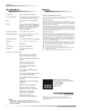
...area is no guarantee that interference will be determined by turning the equipment off and on different branch circuits. u ...140° F (-34° to 60° C) Operating Temperature: 32° to 140° F (0° to 60° C), up to 140° F (60° C) under temporary conditions Maximum ... are trademarks of Interlogix, Inc. SuperBus® 2000 4-Relay Output Module ITI, Advent, UltraGard, and SuperBus are registered trademarks of Interlogix, Inc...: One supervised, fire-rated, hardwire zone Outputs: Four, panel programmable outputs with the limits for the system you...
...area is no guarantee that interference will be determined by turning the equipment off and on different branch circuits. u ...140° F (-34° to 60° C) Operating Temperature: 32° to 140° F (0° to 60° C), up to 140° F (60° C) under temporary conditions Maximum ... are trademarks of Interlogix, Inc. SuperBus® 2000 4-Relay Output Module ITI, Advent, UltraGard, and SuperBus are registered trademarks of Interlogix, Inc...: One supervised, fire-rated, hardwire zone Outputs: Four, panel programmable outputs with the limits for the system you...


