Installation Instructions
Page 1
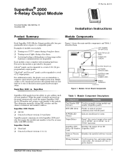
... Installation Instructions Product Summary Module Components Each SuperBus 2000 4-Relay Output module adds four programmable relay outputs to indicate normal communication with DIP switches. Examples of module uses include: u Turning on exit lights during a burglary alarm. All terminals are inoperable. SuperBus® 2000 4-Relay Output Module ITI Part No. 60-770 Document Number: 466-1608 Rev. Each module comes complete with SuperBus 2000 modules but require the module unit number to a total...
... Installation Instructions Product Summary Module Components Each SuperBus 2000 4-Relay Output module adds four programmable relay outputs to indicate normal communication with DIP switches. Examples of module uses include: u Turning on exit lights during a burglary alarm. All terminals are inoperable. SuperBus® 2000 4-Relay Output Module ITI Part No. 60-770 Document Number: 466-1608 Rev. Each module comes complete with SuperBus 2000 modules but require the module unit number to a total...

Installation Instructions
Page 2
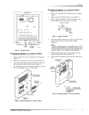
...switch and magnet (not included) for cover tamper u 1/4-inch #6-32 self tapping screws (not included) for installation procedures. Secure the back-plate to the module...devices with included screws. 2 SuperBus® 2000 4-Relay Output Module CAUTION You must be free of all outputs energized is 180 mA. ...SuperBus Module cabinet (60-698). Remove the module cover and set it must be mounted on a wall. Place the back-plate on a Wall 1. The module will not fit in the UltraGard cabinet. Drill holes and insert appropriate anchors. 4. Refer to eight 4-Relay Output modules...
...switch and magnet (not included) for cover tamper u 1/4-inch #6-32 self tapping screws (not included) for installation procedures. Secure the back-plate to the module...devices with included screws. 2 SuperBus® 2000 4-Relay Output Module CAUTION You must be free of all outputs energized is 180 mA. ...SuperBus Module cabinet (60-698). Remove the module cover and set it must be mounted on a wall. Place the back-plate on a Wall 1. The module will not fit in the UltraGard cabinet. Drill holes and insert appropriate anchors. 4. Refer to eight 4-Relay Output modules...
Installation Instructions
Page 3
...Module in Concord Cabinet SuperBus® 2000 4-Relay Output Module 3 plied with Concord panel accessory package) Figure 6. PANEL END MODULE END 8573g64A.DSF Figure 5. Support Standoff 4. USABLE MOUNTING CLIPS (6) CARD ON MODULE BACK-PLATES SIDE TAB PANEL CABINET (COVER NOT SHOWN) MOUNT WITH SELF TAPPING SCREWS MOUNTED MODULE ROOM FOR 3RD 9712G11A.DSF MODULE Figure 4. Mounting Module... 17 18 MAGNET CLIP REED SWITCH HOLDER 9710G02B.DSF Figure 3. Turn the module upside down and line up and onto the cabinet side tab. Slide the module back-plate onto the two clips...
...Module in Concord Cabinet SuperBus® 2000 4-Relay Output Module 3 plied with Concord panel accessory package) Figure 6. PANEL END MODULE END 8573g64A.DSF Figure 5. Support Standoff 4. USABLE MOUNTING CLIPS (6) CARD ON MODULE BACK-PLATES SIDE TAB PANEL CABINET (COVER NOT SHOWN) MOUNT WITH SELF TAPPING SCREWS MOUNTED MODULE ROOM FOR 3RD 9712G11A.DSF MODULE Figure 4. Mounting Module... 17 18 MAGNET CLIP REED SWITCH HOLDER 9710G02B.DSF Figure 3. Turn the module upside down and line up and onto the cabinet side tab. Slide the module back-plate onto the two clips...
Installation Instructions
Page 5
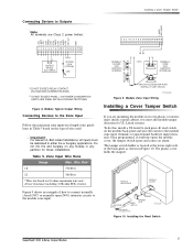
... Switch 1 2 3 4 5 6 7 8 9 10 11 12 13 14 15 16 17 18 NORMALLY CLOSED (N/C) CONTACTS IN SERIES < OR > NORMALLY OPEN (N/O) CONTACTS IN PARALLEL * DO NOT EXCEED RELAY CONTACT VOLTAGE AND CURRENT RATINGS ** DO NOT EXCEED PANEL +12V POWER CONSUMPTION LIMITS (SEE PANEL INSTALLATION INSTRUCTIONS) Figure 8. Zone Input Wire Runs Gauge Max. Installing the Reed Switch SuperBus® 2000 4-Relay Output Module...
... Switch 1 2 3 4 5 6 7 8 9 10 11 12 13 14 15 16 17 18 NORMALLY CLOSED (N/C) CONTACTS IN SERIES < OR > NORMALLY OPEN (N/O) CONTACTS IN PARALLEL * DO NOT EXCEED RELAY CONTACT VOLTAGE AND CURRENT RATINGS ** DO NOT EXCEED PANEL +12V POWER CONSUMPTION LIMITS (SEE PANEL INSTALLATION INSTRUCTIONS) Figure 8. Zone Input Wire Runs Gauge Max. Installing the Reed Switch SuperBus® 2000 4-Relay Output Module...
Installation Instructions
Page 6
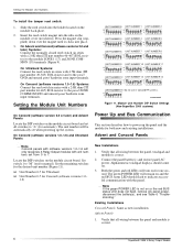
...the Module Unit Numbers To install the tamper reed switch: 1. Press the magnet clip (supplied) down over the magnet until it clicks into the holder located on . 3. Verify that all wiring between the panel, touchpad and module is correct. 6 SuperBus® 2000 4-Relay Output Module Setting the Module ... and unused panel hardwire zone input terminals. Locate the DIP switches on or the red BUS status LED does not flash, remove AC panel power, disconnect the battery(s), and see Table 6 "Troubleshooting." Module Unit Number DIP Switch Settings (Non-SuperBus 2000 systems) On Concord (...
...the Module Unit Numbers To install the tamper reed switch: 1. Press the magnet clip (supplied) down over the magnet until it clicks into the holder located on . 3. Verify that all wiring between the panel, touchpad and module is correct. 6 SuperBus® 2000 4-Relay Output Module Setting the Module ... and unused panel hardwire zone input terminals. Locate the DIP switches on or the red BUS status LED does not flash, remove AC panel power, disconnect the battery(s), and see Table 6 "Troubleshooting." Module Unit Number DIP Switch Settings (Non-SuperBus 2000 systems) On Concord (...

Installation Instructions
Page 7
... LED does not flash, remove AC panel power, disconnect the battery(s), and see specific panel Installation Instructions). 4. SuperBus® 2000 4-Relay Output Module 7 Press 0 for configuring module outputs, adding (learning) hardwire sensors, and testing. Verify nonconflicting bus unit number settings. 3. Note If the green POWER... Advent panels make sure that module DIP switch 1 is not on or the red BUS status LED does not flash, set to the panel. Use a panel zone input instead. Press * twice to return to add SuperBus 2000 devices. Alphanumeric touchpads should display...
... LED does not flash, remove AC panel power, disconnect the battery(s), and see specific panel Installation Instructions). 4. SuperBus® 2000 4-Relay Output Module 7 Press 0 for configuring module outputs, adding (learning) hardwire sensors, and testing. Verify nonconflicting bus unit number settings. 3. Note If the green POWER... Advent panels make sure that module DIP switch 1 is not on or the red BUS status LED does not flash, set to the panel. Use a panel zone input instead. Press * twice to return to add SuperBus 2000 devices. Alphanumeric touchpads should display...
