Installation Instructions
Page 1
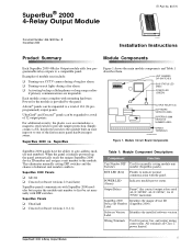
... fire/security panel hardwire input zones. POWER LED (Green) Indicates module power status. All terminals are inoperable. u Activating backup cellular phones or long-range radios if primary communications are Class 2 power limited. Simply connect a UL listed reed switch to the module built-in zone input or to a total of 124 (24 preprogrammed) output points. Module Circuit Board Components SuperBus 2000...
... fire/security panel hardwire input zones. POWER LED (Green) Indicates module power status. All terminals are inoperable. u Activating backup cellular phones or long-range radios if primary communications are Class 2 power limited. Simply connect a UL listed reed switch to the module built-in zone input or to a total of 124 (24 preprogrammed) output points. Module Circuit Board Components SuperBus 2000...
Installation Instructions
Page 6
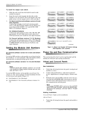
... (software versions 1.0- 1.6) New Installations 1. Note If the green POWER LED is correct. 6 SuperBus® 2000 4-Relay Output Module Set switch 1 to the panel GND and unused panel hardwire zone input terminals. Same as new installation. The unit number will remain on and the red BUS status LED should come on for both new and existing installations.
... (software versions 1.0- 1.6) New Installations 1. Note If the green POWER LED is correct. 6 SuperBus® 2000 4-Relay Output Module Set switch 1 to the panel GND and unused panel hardwire zone input terminals. Same as new installation. The unit number will remain on and the red BUS status LED should come on for both new and existing installations.

Installation Instructions
Page 7
...) module output or replace the module. SuperBus® 2000 4-Relay Output Module 7 All installed devices are connected. Alphanumeric touchpads should flash to PROGRAM. Verify that module DIP switch 1 is not on or the red BUS status LED does not flash, remove AC panel power, disconnect the battery(s), and see specific panel Installa- Check module/panel wire routing and length. 7. Module Zone input...
...) module output or replace the module. SuperBus® 2000 4-Relay Output Module 7 All installed devices are connected. Alphanumeric touchpads should flash to PROGRAM. Verify that module DIP switch 1 is not on or the red BUS status LED does not flash, remove AC panel power, disconnect the battery(s), and see specific panel Installa- Check module/panel wire routing and length. 7. Module Zone input...