Installation Instructions
Page 3
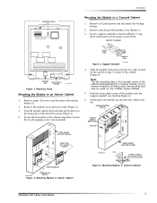
... the cabinet are designated for a receiver module, but if a receiver module is not being used, the mounting clips may be used for the 4-Relay Output Module. 5. Remove AC panel power and disconnect the backup battery. 2. Remove and discard the module cover (Figure 2). 3. Note The two mounting clips in Concord Cabinet SuperBus® 2000 4-Relay Output Module 3 Mounting Module in Figure 5 (sup- MOUNTING...
... the cabinet are designated for a receiver module, but if a receiver module is not being used, the mounting clips may be used for the 4-Relay Output Module. 5. Remove AC panel power and disconnect the backup battery. 2. Remove and discard the module cover (Figure 2). 3. Note The two mounting clips in Concord Cabinet SuperBus® 2000 4-Relay Output Module 3 Mounting Module in Figure 5 (sup- MOUNTING...
Installation Instructions
Page 8
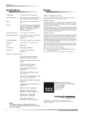
...SuperBus are trademarks of the following measures: u Reorient or relocate the receiving antenna. Storage Temperature: -30° to 140° F (-34° to 60° C) Operating Temperature: 32° to 140° F (0° to 60° C), up to 140° F (60...), 180 mA maximum (all relays energized) Inputs: One supervised, fire-rated, hardwire zone Outputs: Four, panel programmable outputs with the instruction manual, may cause harmful interference to radio communications. These limits are ...is operated in a particular installation. SuperBus® 2000 4-Relay Output Module
...SuperBus are trademarks of the following measures: u Reorient or relocate the receiving antenna. Storage Temperature: -30° to 140° F (-34° to 60° C) Operating Temperature: 32° to 140° F (0° to 60° C), up to 140° F (60...), 180 mA maximum (all relays energized) Inputs: One supervised, fire-rated, hardwire zone Outputs: Four, panel programmable outputs with the instruction manual, may cause harmful interference to radio communications. These limits are ...is operated in a particular installation. SuperBus® 2000 4-Relay Output Module


