Installation Instructions
Page 1
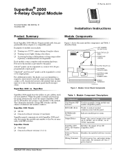
... SuperBus 2000 modules but require the module unit number to first be expanded to provide tamper protection. SuperBus 2000 Identifies the unique device ID Device ID Number (SuperBus 2000). Each module comes complete with the panel. This eliminates manually setting DIP switches and the chance of the fire/security panel hardwire input zones. All terminals are inoperable. SuperBus 2000 vs. SuperBus® 2000 4-Relay Output Module ITI Part No. 60-770...
... SuperBus 2000 modules but require the module unit number to first be expanded to provide tamper protection. SuperBus 2000 Identifies the unique device ID Device ID Number (SuperBus 2000). Each module comes complete with the panel. This eliminates manually setting DIP switches and the chance of the fire/security panel hardwire input zones. All terminals are inoperable. SuperBus 2000 vs. SuperBus® 2000 4-Relay Output Module ITI Part No. 60-770...

Installation Instructions
Page 2
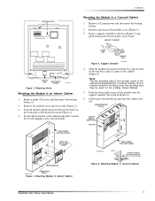
...Wall 1. Secure the back-plate to eight 4-Relay Output modules) u Do not exceed the panel total DC output power ...panel see Table 3). u Inside a SuperBus Module cabinet (60-698). u Inside an Advent cabinet. Tools and Supplies Needed The relay output module can be free of all outputs energized is 180 mA. Mounting the Module Note If connecting the module to the module...SuperBus® 2000 4-Relay Output Module Concord 22 ga. 350 ft./18 ga. 900 ft. u Do not exceed the maximum wire length from the panel to an UltraGard panel it aside (Figure 2). Each module draws 12 mA typical when outputs...
...Wall 1. Secure the back-plate to eight 4-Relay Output modules) u Do not exceed the panel total DC output power ...panel see Table 3). u Inside a SuperBus Module cabinet (60-698). u Inside an Advent cabinet. Tools and Supplies Needed The relay output module can be free of all outputs energized is 180 mA. Mounting the Module Note If connecting the module to the module...SuperBus® 2000 4-Relay Output Module Concord 22 ga. 350 ft./18 ga. 900 ft. u Do not exceed the maximum wire length from the panel to an UltraGard panel it aside (Figure 2). Each module draws 12 mA typical when outputs...
Installation Instructions
Page 3
... Module in an Advent Cabinet 1. Remove and discard the module cover (Figure 2). 3. Mounting Holes Mounting the Module in a Concord Cabinet 1. Secure the back-plate to the cabinet using three ¼-inch #6-32 self-tapping screws (not included). Mounting Module in Figure 6). 6. Remove the module ...center of the cabinet (Figure 6). PANEL END MODULE END 8573g64A.DSF Figure 5. Insert a support standoff as shown in Concord Cabinet SuperBus® 2000 4-Relay Output Module 3 Remove panel AC power and disconnect the backup battery(s). 2. Turn the module upside down and line up and ...
... Module in an Advent Cabinet 1. Remove and discard the module cover (Figure 2). 3. Mounting Holes Mounting the Module in a Concord Cabinet 1. Secure the back-plate to the cabinet using three ¼-inch #6-32 self-tapping screws (not included). Mounting Module in Figure 6). 6. Remove the module ...center of the cabinet (Figure 6). PANEL END MODULE END 8573g64A.DSF Figure 5. Insert a support standoff as shown in Concord Cabinet SuperBus® 2000 4-Relay Output Module 3 Remove panel AC power and disconnect the backup battery(s). 2. Turn the module upside down and line up and ...
Installation Instructions
Page 4
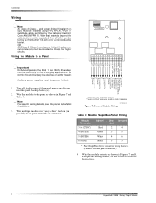
... For specific wiring details, see the device Installation Instructions. 4 SuperBus® 2000 4-Relay Output Module For specific wiring details, see the panel Installation Instructions. 3. Turn off (or disconnect) the panel power and disconnect the panel backup battery(s). 2. Wire multiple modules in "daisy-chain" fashion (in Figures 7 and 8. SUPPLY **ALSO OUTPUT AND AUX. SUPPLY GND (COMMON) 9710G03A.DSF Figure 7. Wire...
... For specific wiring details, see the device Installation Instructions. 4 SuperBus® 2000 4-Relay Output Module For specific wiring details, see the panel Installation Instructions. 3. Turn off (or disconnect) the panel power and disconnect the panel backup battery(s). 2. Wire multiple modules in "daisy-chain" fashion (in Figures 7 and 8. SUPPLY **ALSO OUTPUT AND AUX. SUPPLY GND (COMMON) 9710G03A.DSF Figure 7. Wire...
Installation Instructions
Page 5
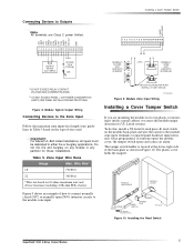
...back-plate as shown in any module in Figure 10. Installing the Reed Switch SuperBus® 2000 4-Relay Output Module 5 Module Zone Input Wiring Installing a Cover Tamper Switch If you must be dedicated to the module zone input. Once programmed, if someone opens the module cover, the tamper switch opens and... UL Listed systems. To do this, install a UL listed ¼-inch press-fit reed switch on the module back-plate and wire the switch to the module zone input terminals or unused panel hardwire input terminals. ZONE COM ZONE 1 GND +12 VDC NO 4 COM 4 NC 4 NO 3 COM 3 NC 3 NO 2 COM ...
...back-plate as shown in any module in Figure 10. Installing the Reed Switch SuperBus® 2000 4-Relay Output Module 5 Module Zone Input Wiring Installing a Cover Tamper Switch If you must be dedicated to the module zone input. Once programmed, if someone opens the module cover, the tamper switch opens and... UL Listed systems. To do this, install a UL listed ¼-inch press-fit reed switch on the module back-plate and wire the switch to the module zone input terminals or unused panel hardwire input terminals. ZONE COM ZONE 1 GND +12 VDC NO 4 COM 4 NC 4 NO 3 COM 3 NC 3 NO 2 COM ...
Installation Instructions
Page 6
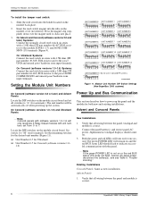
...should come on or the red BUS status LED does not flash, remove AC panel power, disconnect the battery(s), and see Table 6 "Troubleshooting." Set switch 1 to the module ZONE 1 (17) and ZONE COMMON (18) terminals (Figure 9). Same as new installation. Press the magnet clip... between the panel and module is correct. 2. Connect the panel battery(s) and restore panel AC power. Both the green and red LEDs will be automatically set from 0 to power up the system. Verify that all wiring between the panel, touchpad and module is correct. 6 SuperBus® 2000 4-Relay Output Module
...should come on or the red BUS status LED does not flash, remove AC panel power, disconnect the battery(s), and see Table 6 "Troubleshooting." Set switch 1 to the module ZONE 1 (17) and ZONE COMMON (18) terminals (Figure 9). Same as new installation. Press the magnet clip... between the panel and module is correct. 2. Connect the panel battery(s) and restore panel AC power. Both the green and red LEDs will be automatically set from 0 to power up the system. Verify that all wiring between the panel, touchpad and module is correct. 6 SuperBus® 2000 4-Relay Output Module

Installation Instructions
Page 7
..., disconnect the battery(s), and see specific panel Installa- Use a panel zone input instead. Reprogram using a different (unused) module output or replace the module. Connect the panel battery(s) and restore panel AC power. Press * twice to return to "A." 4. UltraGard Panels 1. Module Zone input 1. is flashing, you must enter the 4-digit installer access code to add SuperBus 2000 devices. One output stays activated. 1. Alphanumeric touchpad displays...
..., disconnect the battery(s), and see specific panel Installa- Use a panel zone input instead. Reprogram using a different (unused) module output or replace the module. Connect the panel battery(s) and restore panel AC power. Press * twice to return to "A." 4. UltraGard Panels 1. Module Zone input 1. is flashing, you must enter the 4-digit installer access code to add SuperBus 2000 devices. One output stays activated. 1. Alphanumeric touchpad displays...
Installation Instructions
Page 8
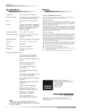
...all relays energized) Inputs: One supervised, fire-rated, hardwire zone Outputs: Four, panel programmable outputs with the instructions, may cause harmful interference to correct the ...176; to 140° F (-34° to 60° C) Operating Temperature: 32° to 140° F (0° to 60° C), up to 140° F (60° C) under temporary conditions Maximum Humidity: 90% relative... be required to radio communications. SuperBus® 2000 4-Relay Output Module However, there is likely to cause harmful interference in panel cabinet mounting Listings (for ancillary use...
...all relays energized) Inputs: One supervised, fire-rated, hardwire zone Outputs: Four, panel programmable outputs with the instructions, may cause harmful interference to correct the ...176; to 140° F (-34° to 60° C) Operating Temperature: 32° to 140° F (0° to 60° C), up to 140° F (60° C) under temporary conditions Maximum Humidity: 90% relative... be required to radio communications. SuperBus® 2000 4-Relay Output Module However, there is likely to cause harmful interference in panel cabinet mounting Listings (for ancillary use...

